Crew Cab
Wing Nut Retaining Tool Kit
Tool Kit
Wheel Blocks
Jack
Jack Knob
Wing Nut Retaining Wheel Blocks
Regular Cab
Wing Nut Retaining Tool Kit
Tool Kit
Wheel Blocks
Jack
Jack Knob
Wing Nut Retaining Wheel Blocks
Extended Cab
Wing Nut Retaining Tool Kit
Tool Kit
Wheel Blocks
Jack
Jack Knob
For regular cab models, the equipment you will need is behind the passenger's seat. For extended and crew cab models, the equipment is on the shelf behind the passenger's side second row seat.
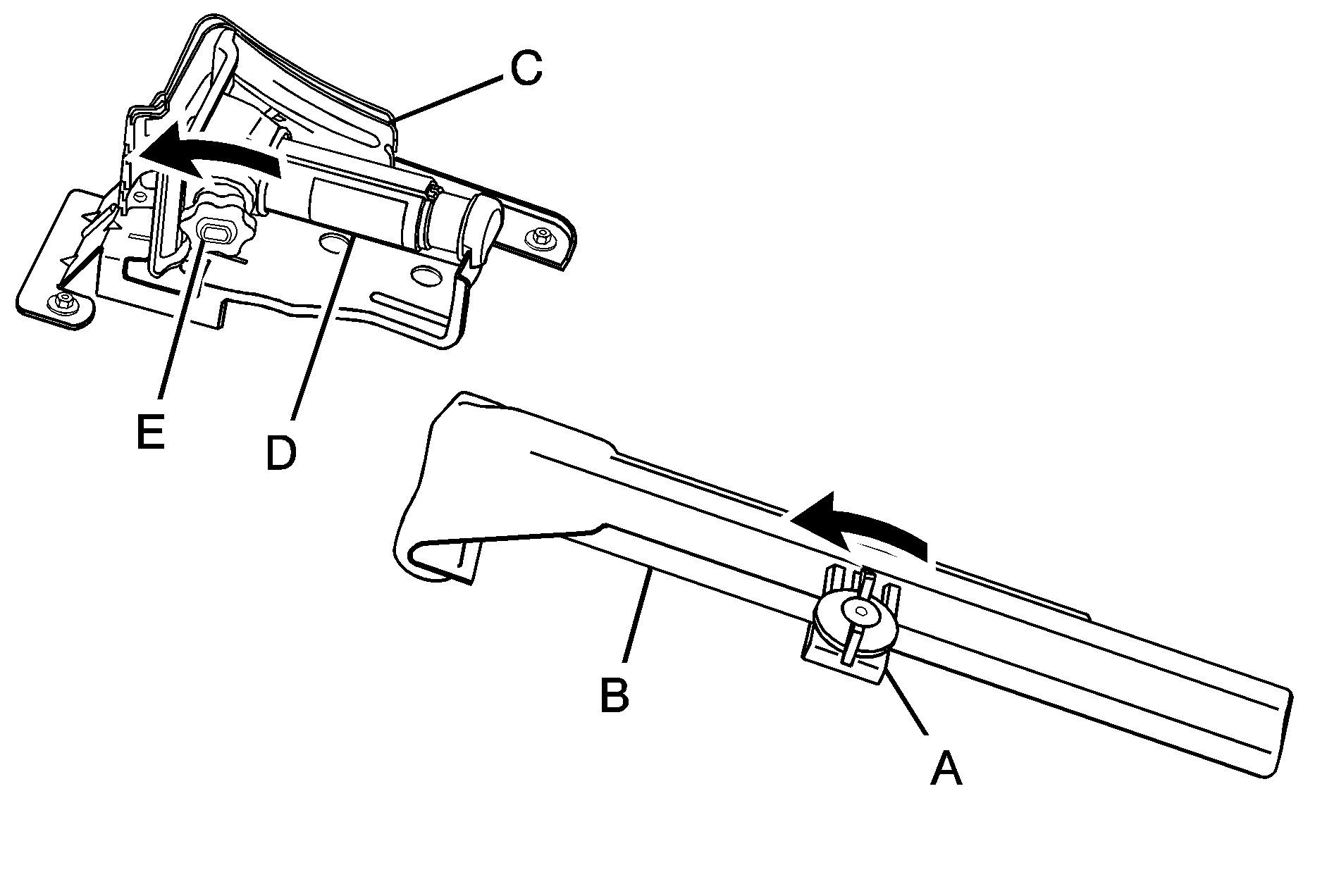
- Turn the knob on the jack counterclockwise to lower the jack head to release the jack from its holder.
- Remove the wheel blocks and the wheel block retainer by turning the wing nut counterclockwise.
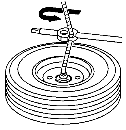
- Remove the wing nut used to retain the storage bag and tools by turning it counterclockwise.
You will use the jack handle extensions and the wheel wrench to remove the underbody-mounted spare tire.
-
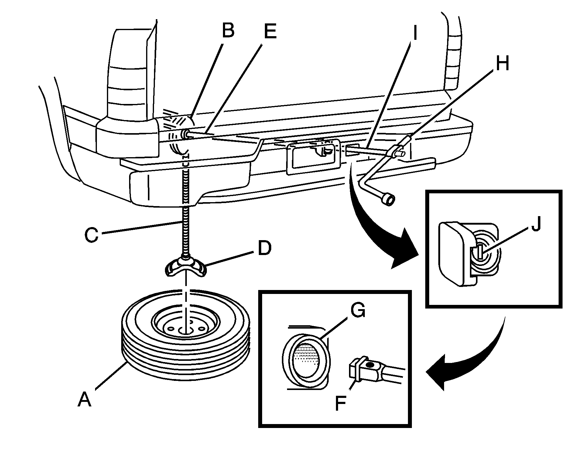
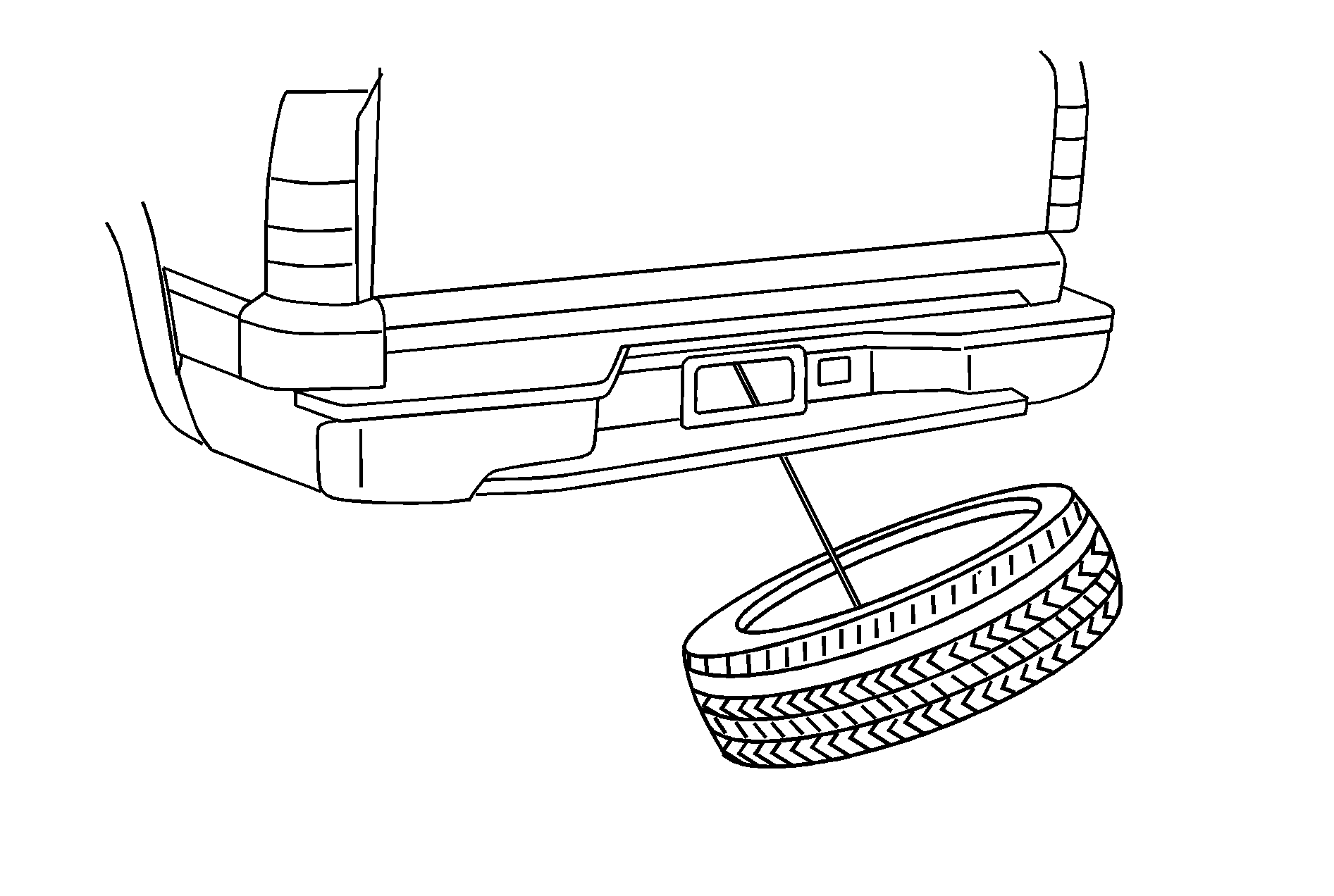
Spare Tire (Valve Stem Pointed Down)
Hoist Assembly
Hoist Cable
Tire/Wheel Retainer
Hoist Shaft
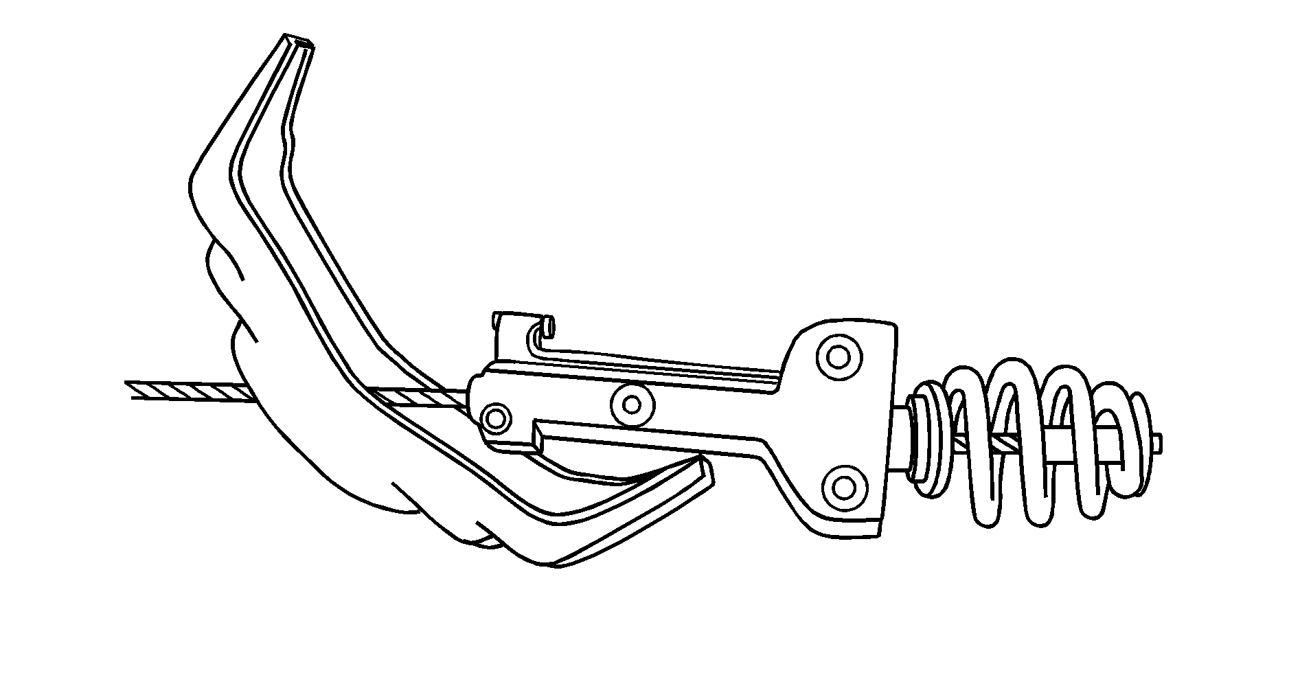
Hoist End of Extension Tool
Hoist Shaft Access Hole
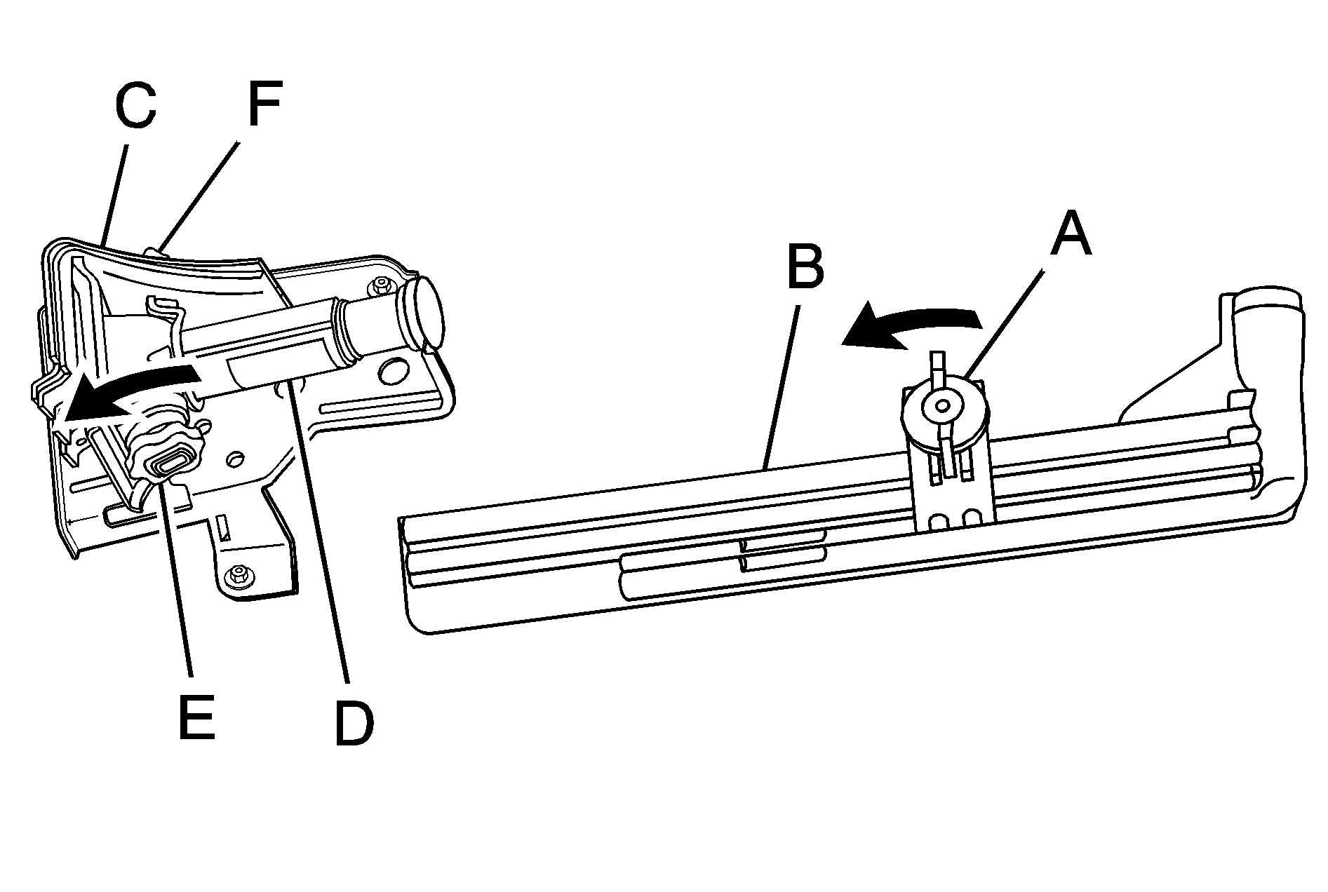
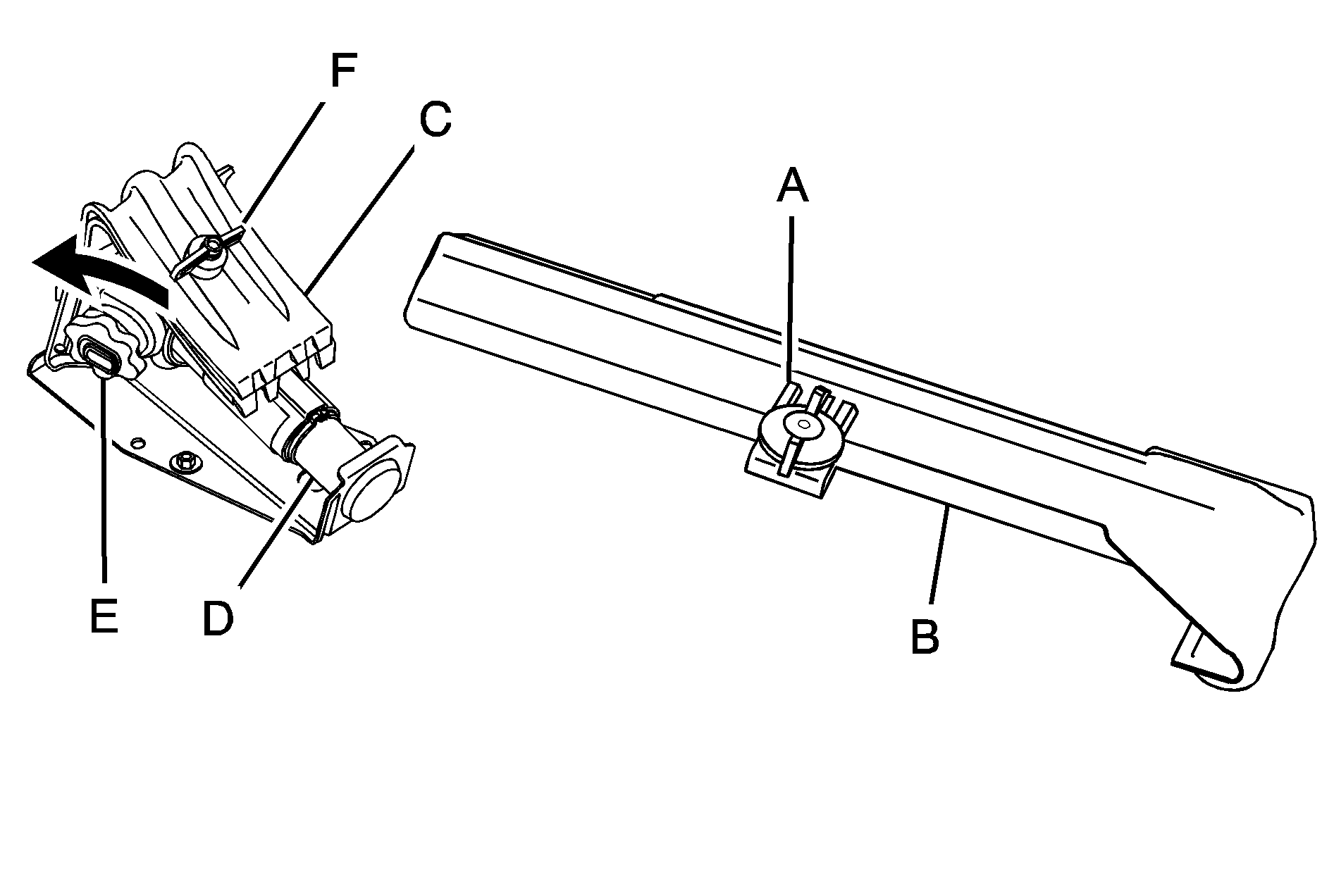
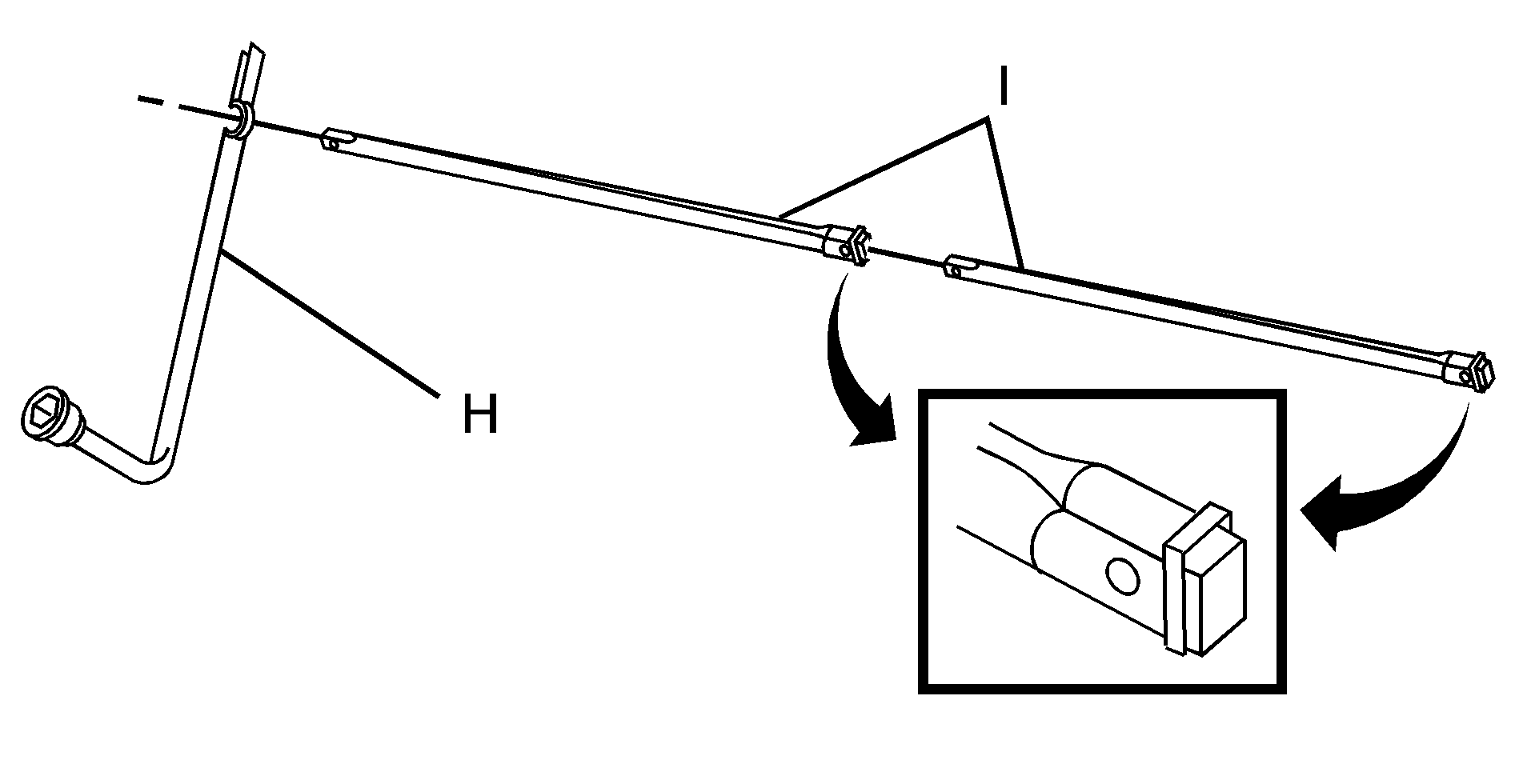
Wheel Wrench
Jack Handle Extensions
Spare Tire Lock (If equipped)
- Open the spare tire lock cover on the bumper and use the ignition key to remove the spare tire lock (J). To remove the spare tire lock, insert the ignition key turn and pull straight out.
- Assemble the wheel wrench (H) and the two jack handle extensions (I) as shown.
- Be sure the hoist end of the extension (F) connects to the hoist shaft (E). The ribbed square end of the extension is used to lower the spare tire.
- Turn the wheel wrench (H) counterclockwise to lower the spare tire to the ground. Continue to turn the wheel wrench until the spare tire can be pulled out from under the vehicle.
- Tilt the tire toward the vehicle with some slack in the cable to access the tire/wheel retainer. Separate the retainer from the guide pin by sliding the retainer up the pin while pressing down on the latch.
- Once the retainer is separated from the guide pin, tilt the retainer and pull it through the center of the wheel along with the cable and guide latch.
- Put the spare tire near the flat tire.
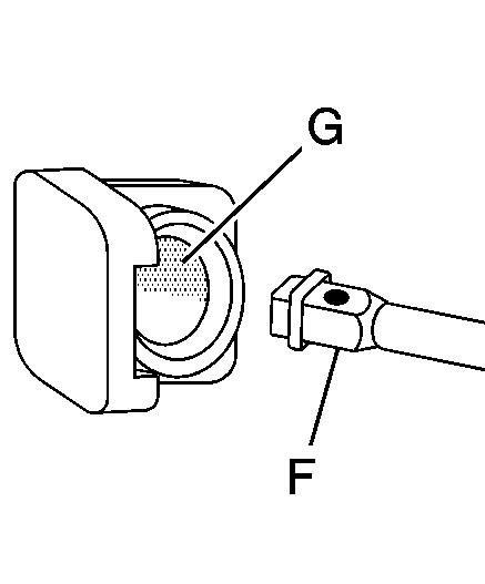
Insert the hoist end (open end) (F) of the extension through the hole (G) in the rear bumper.
Do not use the chiseled end of the wheel wrench.
If the spare tire does not lower to the ground, the secondary latch is engaged causing the tire not to lower. See Secondary Latch System.
Use the wheel wrench hook which allows you to pull the hoist cable towards you to assist in reaching the spare tire.