Pickup Box Outer Side Panel Replacement Bond-On
Removal Procedure
Important: This adhesive bonding procedure represents one manufacturer's installation application. Other manufacturers' procedures may vary, including MIG welding in some areas of the repair. Always follow the system manufacturer's instructions for application, handling, and curing.
Important: Before you begin the repair, refer to Metal Panel Bonding for proper adhesive preparations and general information.
- Remove the box assembly. Refer to Pickup Box Replacement .
- Remove the endgate. Refer to Endgate Replacement .
- Remove the tail lamp. Refer to Tail/Turn Signal Lamp Replacement .
- Repair as much or the damage as possible, according to factory specifications.
- Note the location and remove the sealers and anti-corrosion materials from the repair area, as necessary. Refer to Anti-Corrosion Treatment and Repair .
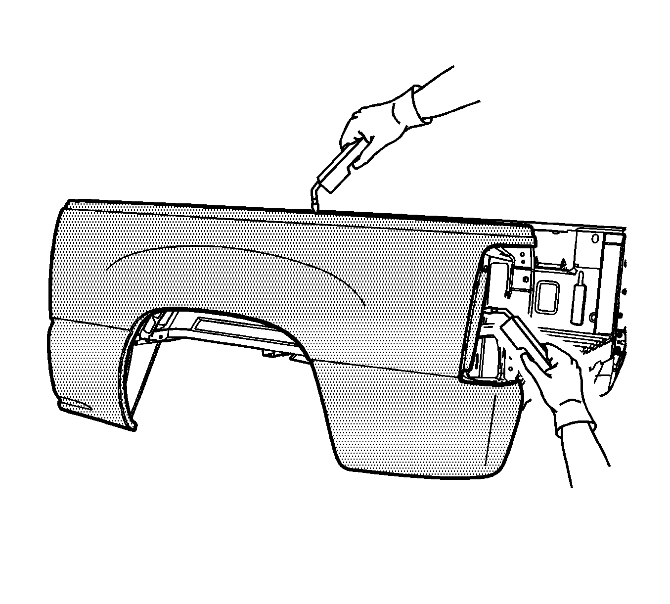
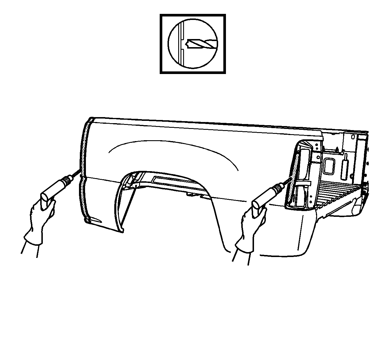
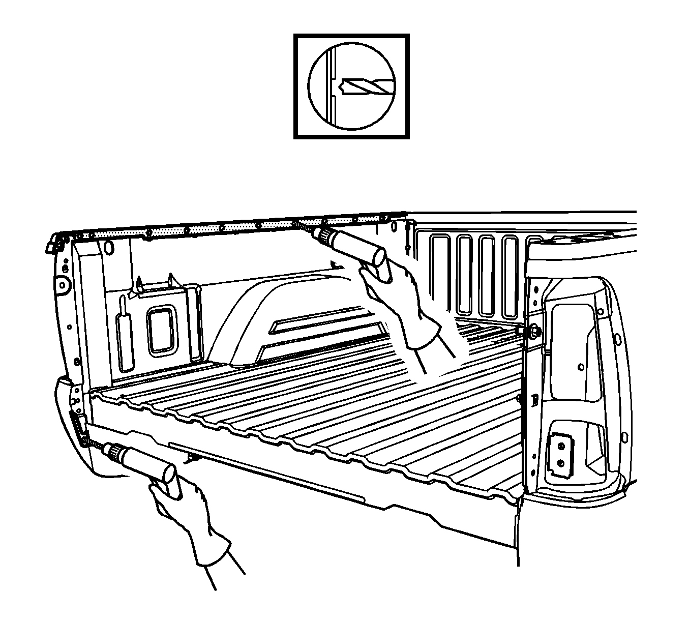
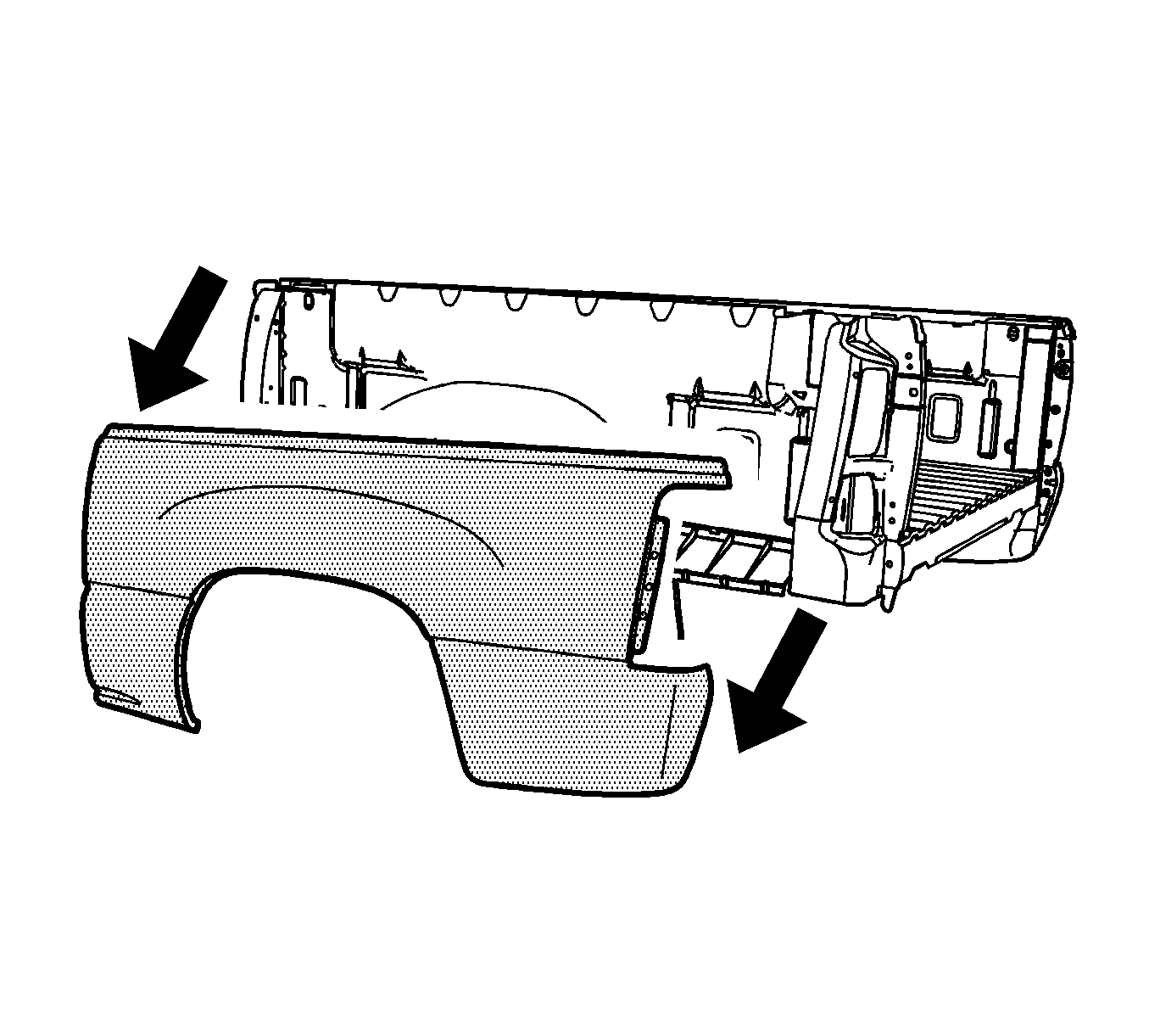
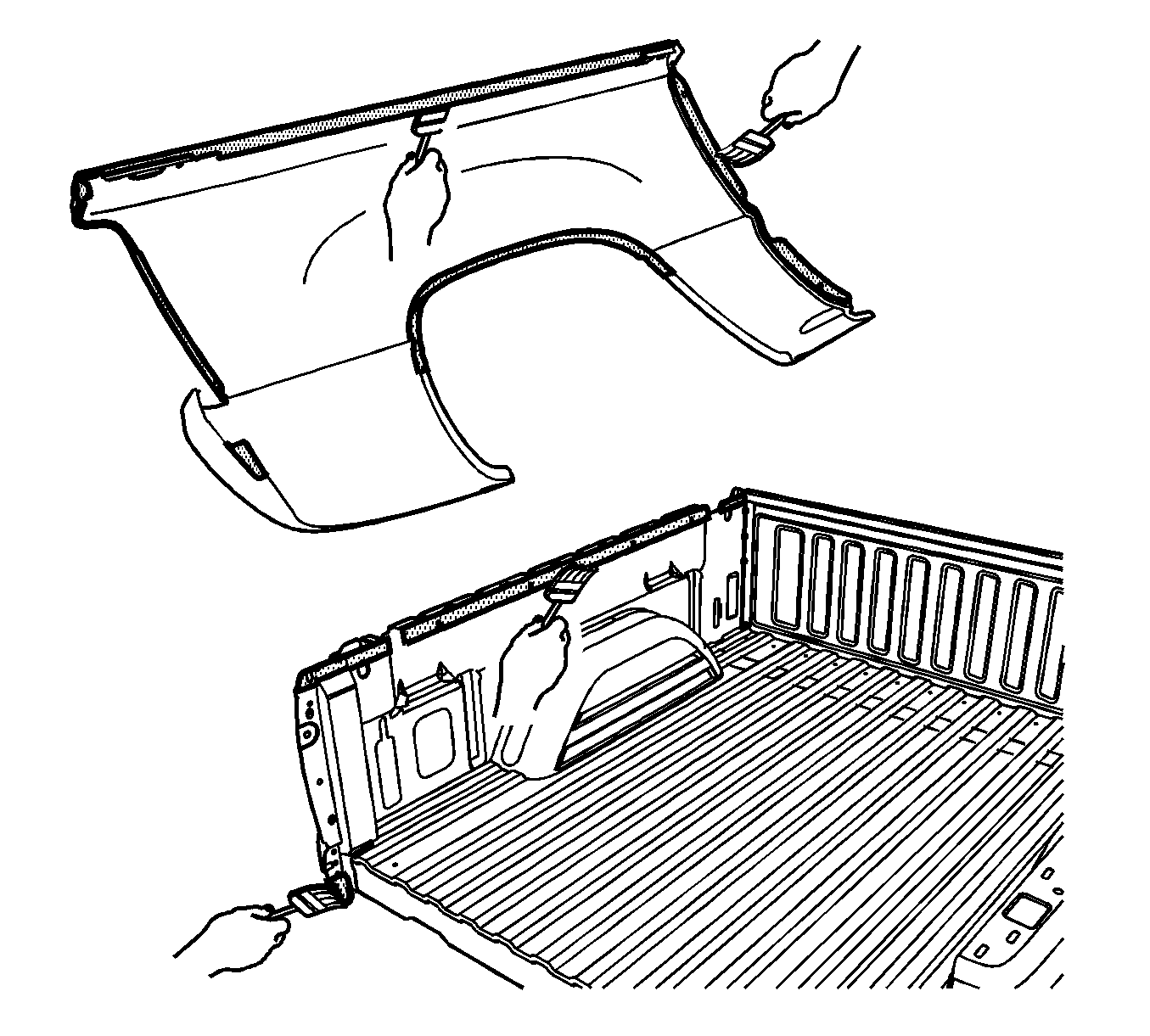
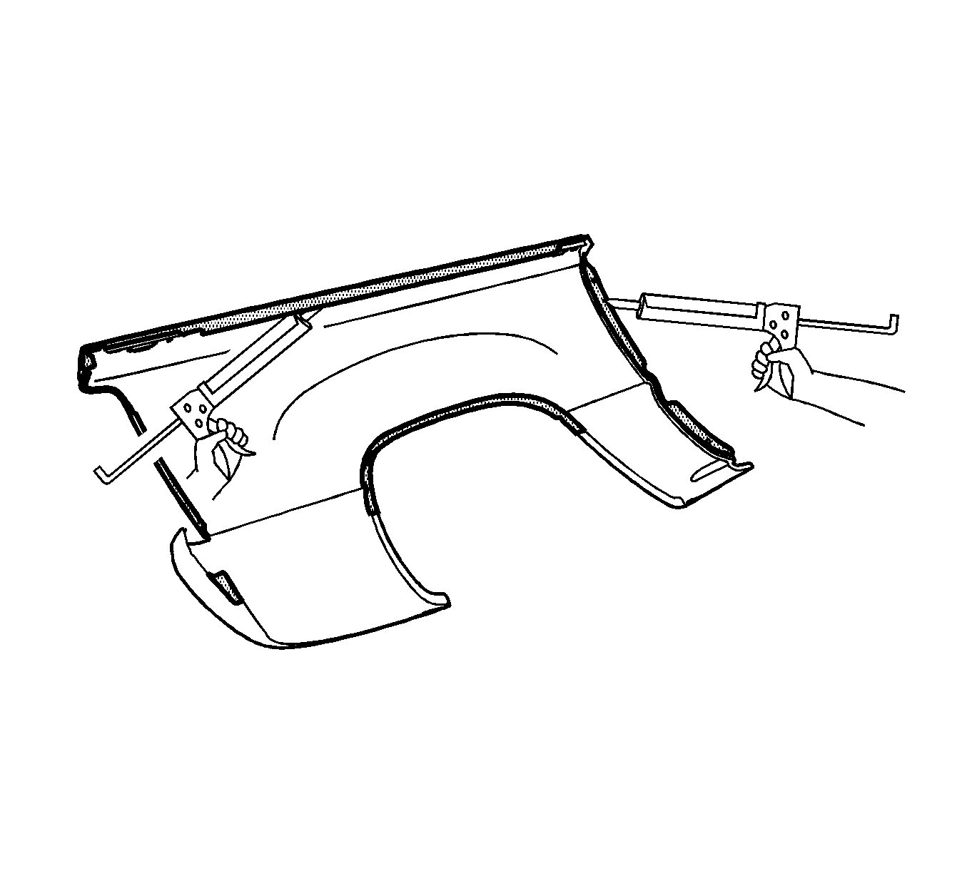
- Locate and drill out the spot welds attaching the front panel, the wheelhouse, and the tail lamp pocket area.
- Locate and drill out spot welds on the upper rail.
- Remove the side panel.
Caution: Refer to Approved Equipment for Collision Repair Caution in the Preface section.
Installation Procedure
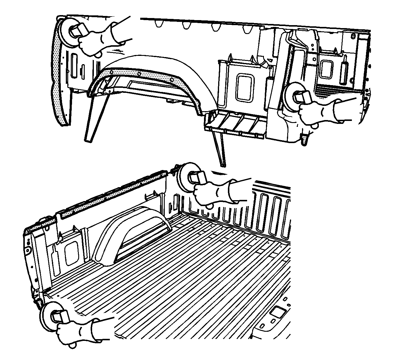
- Grind the surface of the bed assembly mating flanges to bare steel. Do not damage the corners or thin the metal during the grinding process.
- Grind the mating flanges of the service side panel to remove the E-coating. Do not damage the corners or thin the metal during the grinding operation.
- Clean the mating surfaces.
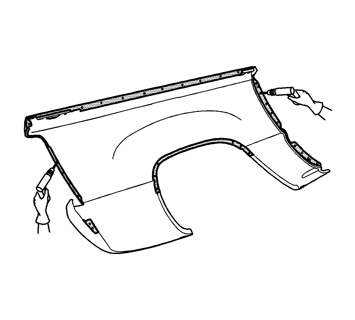
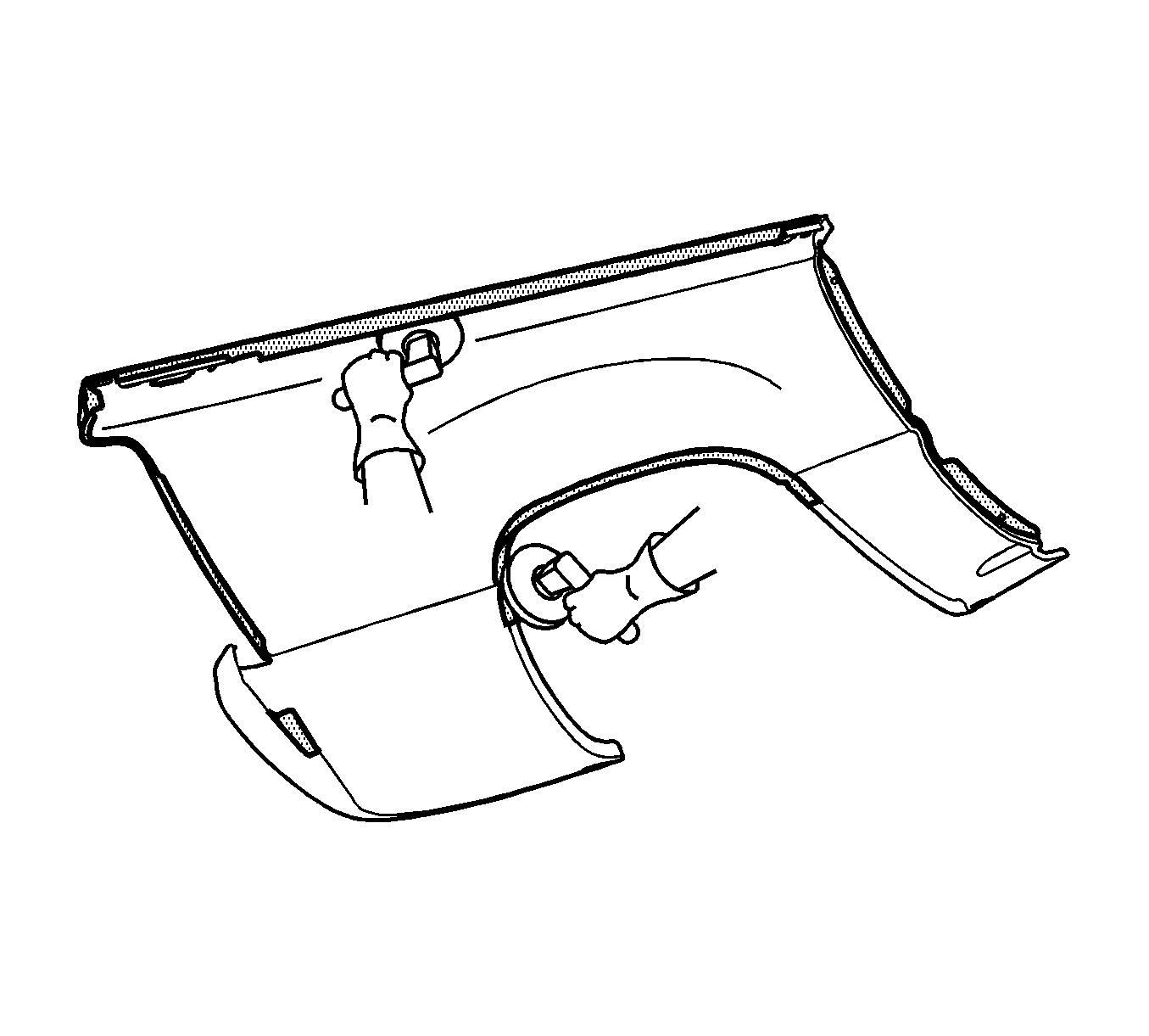
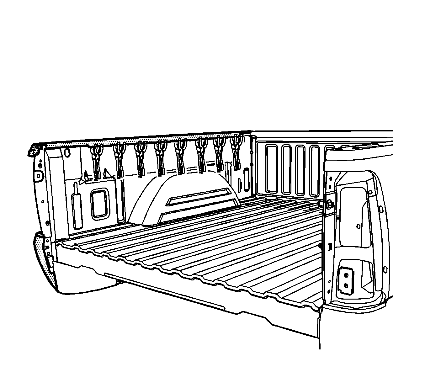
- Apply a 3 to 6-mm (1/8 to 1/4-in) bead of metal panel bonding adhesive to both of the mating surfaces.
- Using a small acid brush, spread a coat of adhesive to both of the mating surfaces. Cover all of the bare metal to ensure corrosion protection.
- Apply a 9 to 13-mm (3/8 to 1/2-in) bead of metal panel bonding adhesive to the mating surface of the service side panel.
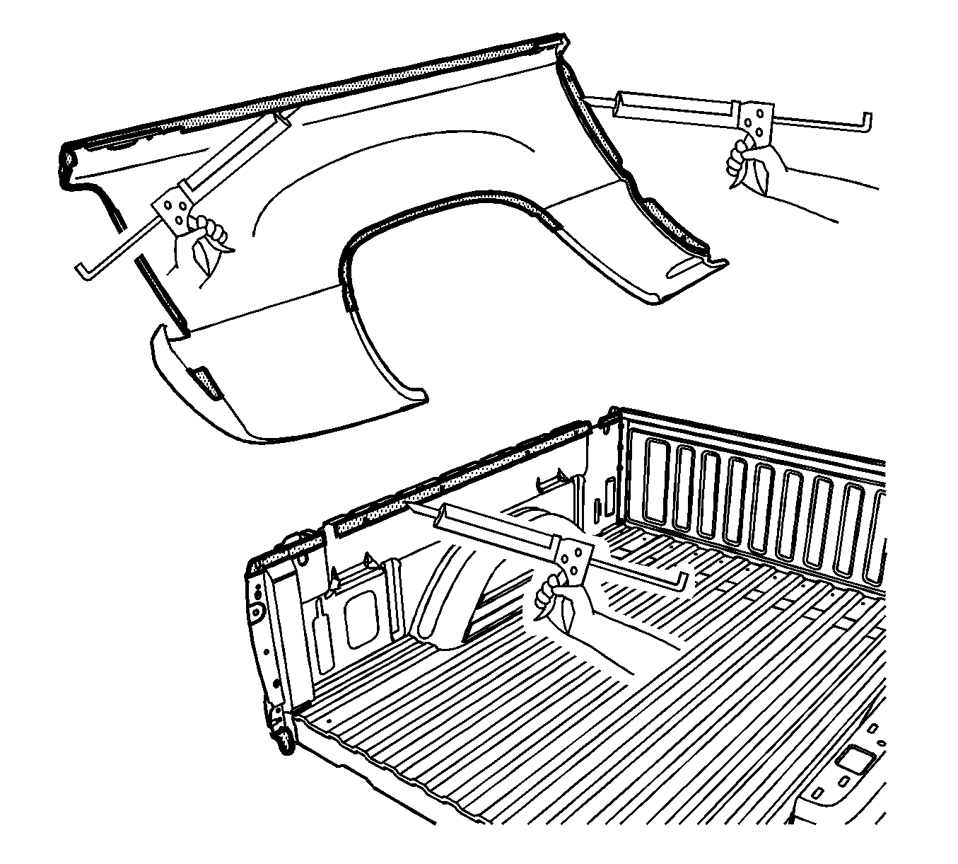
- Position the service side panel to the bed assembly.
- Clamp the service side panel into position.
- Using lacquer thinner remove the excess adhesive from the bed side panel area.
- Apply the sealers and anti-corrosion materials to the repair area, as necessary. Refer to Anti-Corrosion Treatment and Repair .
- Paint the repair area. Refer to Basecoat/Clearcoat Paint Systems .
- Install the tail lamp. Refer to Tail/Turn Signal Lamp Replacement .
- Install the endgate. Refer to Endgate Replacement .
- Install the box assembly. Refer to Pickup Box Replacement .
Important: Do not allow the adhesive to cure prior to installing the service side panel.

Important: Do NOT pull the panels apart after you have joined the panels together. Slide the panels against each other to realign the panels.
Pickup Box Outer Side Panel Replacement Weld-On
Removal Procedure
- Remove the box assembly. Refer to Pickup Box Replacement .
- Remove the endgate. Refer to Endgate Replacement .
- Remove the tail lamp. Refer to Tail/Turn Signal Lamp Replacement .
- Repair as much of the damage as possible, according to factory specifications.
- Note the location and remove the sealers and anti-corrosion materials from the repair area, as necessary. Refer to Anti-Corrosion Treatment and Repair .
- Note the number and location of all spot welds to be drilled out for installation of the service part.
- Locate and drill out the spot welds attaching the front panel wheelhouse and the tail lamp pocket area.
- Locate and drill out the spot welds on the upper rail.
- Remove the side panel.
Caution: Refer to Approved Equipment for Collision Repair Caution in the Preface section.
Installation Procedure
- Drill 8-mm (5/16-in) plug weld holes in the service part as noted.
- Prepare all mating surfaces as necessary.
- Apply Weld-Thru Coating to all mating surfaces.
- Position the service part onto the bed assembly.
- Plug weld as necessary
- Clean and prepare all welded surfaces.
- Apply the sealers and anti-corrosion materials to the repair area, as necessary. Refer to Anti-Corrosion Treatment and Repair .
- Paint and repair the area. Refer to Basecoat/Clearcoat Paint Systems .
- Install the tail lamp. Refer to Tail/Turn Signal Lamp Replacement .
- Install the endgate. Refer to Endgate Replacement .
- Install the box assembly. Refer to Pickup Box Replacement .