DTC P1870 Transmission Component Slipping 2.2L
Circuit Description
The powertrain control module (PCM) monitors the difference between
engine speed and transmission output speed. In D3 drive range with the TCC
engaged, the engine speed should closely match the transmission output speed.
In D4 drive range, with the TCC engaged, the TCC slip speed should be -20
to +60 RPM.
When the PCM detects excessive TCC slip when the TCC should be engaged,
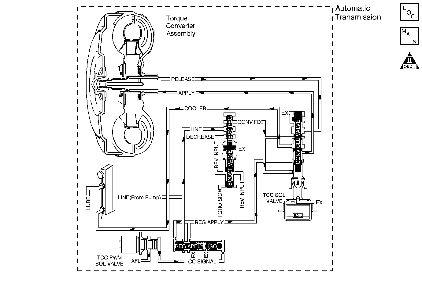
then DTC P1870 sets. DTC P1870 is a type B DTC.
Conditions for Running the DTC
| • | No TP sensor DTCs P0122 or P0123. |
| • | No VSS assembly DTCs P0502 or P0503. |
| • | No TCC solenoid valve DTC P0740. |
| • | No 1-2 SS valve DTC P0753. |
| • | No 2-3 SS valve DTC P0758. |
| • | No 3-2 SS valve assembly DTC P0785. |
| • | No TCC PWM solenoid valve DTC P1860. |
| • | The engine is not in fuel cutoff. |
| • | The engine torque is 40-400 lb ft. |
| • | The TP angle is 12-50%. |
| • | The vehicle speed is 56-112 km/h (35-70 mph). |
| • | The speed ratio is 0.64-0.95 (the speed ratio is the engine
speed divided by the transmission output speed). |
| • | The engine speed is 1500-3500 RPM. |
| • | The commanded gear is not 1st gear |
| • | The TFT is between 20-130°C (68-266°F). |
| • | The shift solenoid performance diagnostic counters are zero. |
Conditions for Setting the DTC
DTC P1870 sets if the following conditions occur for three TCC
cycles during the same trip.
| • | The TCC is commanded ON for 5 seconds. |
| • | The TCC is at maximum duty cycle for 8.5 seconds. |
| • | The TCC slip speed is 300-1000 RPM for 7 seconds. |
| | Important: The following actions may occur before the DTC sets.
|
| • | If the TCC is commanded ON and at maximum duty cycle for 8.5 seconds,
the TP angle is 7-40%, and the transmission slip counter has incremented
to either 1 or 2 (out of 3 to increment the fail counter for the current ignition
cycle), then the following slip conditions and actions may increment the fail
counter for the current ignition cycle: |
| | These conditions must
occur sequentially. |
| - | Condition 1:
If the TCC slip speed is
200-1000 RPM for 7 seconds, then the PCM commands maximum
line pressure and freezes shift adapts from being updated. |
| - | Condition 2:
If Condition 1 is met and
the TCC slip speed is 200-1000 RPM for 7 seconds, then
the PCM commands the TCC OFF for 1.5 seconds. |
| - | Condition 3:
If Condition 2 is met and
the TCC slip speed is 200-1000 RPM for 7 seconds, then
the fail counter on the current ignition cycle is incremented. |
| - | The above slip conditions and actions may be disregarded if the TCC is commanded
OFF at any time as a result of a driving maneuver (sudden acceleration or
deceleration). |
Action Taken When the DTC Sets
| • | The PCM illuminates the malfunction indicator lamp (MIL) during
the second consecutive trip in which the Conditions for Setting the DTC are
met. |
| • | The PCM commands maximum line pressure. |
| • | The PCM inhibits TCC engagement. |
| • | The PCM inhibits 4th gear if the transmission is in hot mode. |
| • | The PCM freezes shift adapts from being updated. |
| • | the PCM records the operating conditions when the Conditions for
Setting the DTC are met. The PCM stores this information as Freeze Frame and
Failure Records. |
| • | The PCM stores DTC P1870 in PCM history during the second
consecutive trip in which the Conditions for Setting the DTC are met. |
Conditions for Clearing the MIL/DTC
| • | The PCM turns OFF the MIL during the third consecutive trip in
which the diagnostic test runs and passes. |
| • | A scan tool can clear the MIL/DTC. |
| • | The PCM clears the DTC from PCM history if the vehicle completes
40 warm-up cycles without an emission-related diagnostic fault
occurring. |
| • | The PCM cancels the DTC default actions when the fault no longer
exists and/or the ignition switch is OFF long enough in order to power down
the PCM. |
Diagnostic Aids
| • | Bronze material found in the transmission oil pan may indicate
stator shaft bushing wear. If bushing wear is suspected, inspect the stator
shaft and the input (turbine) shaft for damage. |
Test Description
The numbers below refer to the step numbers on the diagnostic table.
-
This step tests the torque converter for
slippage while in a commanded lock-up state.
DTC P1870 Transmission Component Slipping (2.2L)
Step
| Action
| Value(s)
| Yes
| No
|
1
| Did you perform the Powertrain
Diagnostic System Check?
| --
|
Go to Step 2
| Go to
Powertrain On Board Diagnostic (OBD) System Check
(2.2L) in Engine Controls
|
2
| Inspect for correct transmission
fluid level.
Refer to
Transmission Fluid Check
.
Did you perform the fluid checking procedure?
| --
|
Go to Step 3
| Go to
Transmission Fluid Check
|
3
|
- Install a Scan Tool
.
- Turn ON the ignition, with the engine OFF.
Important: Before clearing the DTC, use the Scan Tool
in order to record the Freeze Frame and Failure Records.
Using the Clear Info function erases the Freeze Frame and Failure Records
from the PCM.
- Record the DTC Freeze Frame and Failure Records.
- Clear the DTC.
Important: It may be necessary to allow multiple TCC cycles to occur in order to
verify a slipping condition. It may also be necessary to ensure the transmission
is warm before performing this step.
- Drive the vehicle in 4th gear with the TCC commanded ON.
Does the Scan Tool
TCC Slip Speed measure within the specified range for 7 seconds?
| 300-1000 RPM
|
Go to Step 4
| Go to Diagnostic Aids
|
4
|
- Inspect the torque converter clutch (TCC) solenoid valve for the
following conditions:
| • | Internal malfunction (such as sediment or damage) |
- Inspect the torque converter clutch pulse width modulation (TCC PWM)
solenoid valve for the following conditions:
| • | Internal malfunction (such as sediment or damage) |
Did you find and correct the condition?
| --
|
Go to Step 14
|
Go to Step 5
|
5
|
- Inspect the 1-2 shift solenoid (SS) valve for the following conditions:
| • | Internal malfunction (such as sediment or damage) |
- Inspect the 2-3 SS valve for the following conditions:
| • | Internal malfunction (such as sediment or damage) |
- Inspect the 3-2 shift solenoid valve assembly for the following
conditions:
| • | Internal malfunction (such as sediment or damage) |
Did you find and correct the condition?
| --
|
Go to Step 14
|
Go to Step 6
|
6
|
- Inspect the valve body assembly for a stuck regulator apply valve.
- Inspect the valve body assembly for a scored regulator apply valve
body.
Refer to
Transmission Overhaul
in the 4L60-E Section of the Transmission Unit
Repair Manual.
Did you find and correct the condition?
| --
|
Go to Step 13
|
Go to Step 7
|
7
| Inspect the torque converter assembly for the following conditions:
| • | Front stator shaft bushing for wear |
| • | Stator roller clutch not holding |
Did you find and correct the condition?
| --
|
Go to Step 13
|
Go to Step 8
|
8
| Inspect the oil pump assembly for the following conditions:
| • | Stuck converter clutch valve |
| • | Converter clutch valve assembled backwards |
| • | Mispositioned converter clutch valve retaining ring |
| • | Cocked converter clutch outer valve spring |
| • | Mispositioned pump to case gasket |
| • | Restricted orifice cup plugs |
| • | Damaged orifice cup plugs |
| • | Over-tightened, or unevenly tightened pump body to cover bolts |
Refer to
Transmission Overhaul
in the 4L60-E
Section of the Transmission Unit Repair Manual.
Did you find and correct the condition?
| --
|
Go to Step 13
|
Go to Step 9
|
9
| Inspect the input housing and shaft assembly for the following conditions:
| • | Cut turbine shaft O-ring seal |
| • | Damaged turbine shaft O-ring seal |
| • | Restricted turbine shaft retainer and ball assembly |
| • | Damaged turbine shaft retainer and ball assembly |
Refer to
Transmission Overhaul
in the 4L60-E
Section of the Transmission Unit Repair Manual.
Did you find and correct the condition?
| --
|
Go to Step 13
|
Go to Step 10
|
10
| Inspect the 2-4 band assembly for the following conditions:
| • | The band anchor pin is not engaged. |
| • | Restricted apply passages in the 2-4 servo assembly |
| • | Blocked apply passages in the 2-4 servo assembly |
| • | Nicks or burrs on the servo pin |
| • | Nicks or burrs on the pin bore in the case |
| • | Damaged fourth servo piston |
| • | Misassembled fourth servo piston |
| • | Incorrect band apply pin |
| • | Damaged servo bore in the case |
| • | Porosity in the pistons |
| • | Damaged piston seal grooves |
| • | Plugged orifice cup plug |
| • | Missing orifice cup plug |
Refer to
Transmission Overhaul
in the 4L60-E
Section of the Transmission Unit Repair Manual.
Did you find and correct the condition?
| --
|
Go to Step 13
|
Go to Step 11
|
11
| Inspect the forward clutch assembly for the following conditions:
| • | Porosity in the forward clutch piston |
| • | Damaged forward clutch piston |
| • | Missing forward clutch piston inner and outer seals |
| • | Cut forward clutch piston inner and outer seals |
| • | Damaged forward clutch piston inner and outer seals |
| • | Missing input housing to forward clutch housing O-ring seal |
| • | Cut input housing to forward clutch housing O-ring seal |
| • | Damaged input housing to forward clutch housing O-ring seal |
| • | Damaged forward clutch housing |
| • | Damaged forward clutch housing retainer and ball assembly |
| • | Forward clutch housing retainer and ball assembly is not sealing. |
Refer to
Transmission Overhaul
in the 4L60-E
Section of the Transmission Unit Repair Manual.
Did you find and correct the condition?
| --
|
Go to Step 13
|
Go to Step 12
|
12
| Inspect the 3-4 clutch assembly for the following conditions:
| • | Porosity in the 3-4 clutch piston |
| • | Damaged 3-4 clutch piston |
| • | Missing 3-4 clutch inner and outer seals |
| • | Cut 3-4 clutch inner and outer seals |
| • | Damaged 3-4 clutch inner and outer seals |
| • | Damaged 3-4 clutch spring assembly |
| • | Damaged 3-4 clutch apply ring |
| • | Damaged piston seal grooves |
| • | Plugged orifice cup plug |
| • | Missing orifice cup plug |
Refer to
Transmission Overhaul
in the 4L60-E
Section of the Transmission Unit Repair Manual.
Did you find and correct the condition?
| --
|
Go to Step 13
| Go to Diagnostic Aids
|
13
|
- Change the AT fluid and filter.
- Inspect for correct transmission fluid level.
Refer
to
Transmission Fluid Check
.
- Add new AT fluid as necessary.
Important: The Clear TAPS function will clear all adapt cells. This may affect
transmission performance. The PCM will update the transmission adapt cell
values as the vehicle is driven.
- Using the Scan Tool
,
perform the Clear TAPS function.
Did you complete the above procedure?
| --
|
Go to Step 14
| --
|
14
| Perform
the following procedure in order to verify the repair:
- Select DTC.
- Select Clear Info.
- Operate the vehicle under the following conditions:
| • | Drive the vehicle in D4, with the TCC ON, and a throttle position
of 12-50%. |
| • | Ensure that the Scan Tool
TCC Slip Speed is -20 to +60 RPM for at least 7 seconds. |
- Select Specific DTC.
- Enter DTC P1870.
Has the test run and passed?
| --
| System OK
|
Go to Step
1
|
DTC P1870 Transmission Component Slipping 4.3L
Circuit Description
The vehicle control module (VCM) monitors the difference between engine
speed and transmission output speed. In D3 drive range with the TCC engaged,
the engine speed should closely match the transmission output speed. In D4
drive range, with the TCC engaged, the TCC slip speed should be -20
to +50 RPM.
When the VCM detects excessive TCC slip when the TCC should be engaged,
then DTC P1870 sets. DTC P1870 is a type B DTC.
Conditions for Running the DTC
| • | No TP sensor DTCs P0122 or P0123. |
| • | No VSS assembly DTCs P0502 or P0503. |
| • | No TFT sensor DTCs P0711, P0712 or P0713. |
| • | No TCC solenoid valve DTC P0740. |
| • | No 1-2 SS valve DTC P0753. |
| • | No 2-3 SS valve DTC P0758. |
| • | No TFP manual valve position switch DTC P1810. |
| • | No TCC PWM solenoid valve DTC P1860. |
| • | The engine speed is greater than 450 RPM for 5 seconds. |
| • | The engine is not in fuel cutoff. |
| • | The engine torque is 50-400 lb ft. |
| • | The engine vacuum is 0-150 kPa. |
| • | The vehicle speed is 48-112 km/h (30-70 mph). |
| • | The engine speed is 1500-3000 RPM. |
| • | The speed ratio is 0.69-0.88 (speed ratio is engine speed
divided by the output speed). |
| • | The commanded gear is not 1st gear. |
| • | The TFT is 20-130°C (68-266°F). |
| • | The shift solenoid performance diagnostic counters are zero. |
Conditions for Setting the DTC
DTC P1870 sets if the following conditions occur for three TCC
cycles.
| • | The TCC is commanded ON for 5 seconds. |
| • | The TCC is at maximum duty cycle (95%) for 5 seconds. |
| • | The TCC slip speed is 130-800 RPM for 7 seconds. |
Action Taken When the DTC Sets
| • | The VCM illuminates the malfunction indicator lamp (MIL) during
the second consecutive trip in which the Conditions for Setting the DTC are
met. |
| • | The VCM commands maximum line pressure. |
| • | The VCM inhibits TCC engagement. |
| • | The VCM inhibits 4th gear if the transmission is in hot mode. |
| • | The VCM freezes shift adapts from being updated. |
| • | The VCM records the operating conditions when the Conditions for
Setting the DTC are met. The VCM stores this information as Freeze Frame and
Failure Records. |
| • | The VCM stores DTC P1870 in VCM history during the second
consecutive trip in which the Conditions for Setting the DTC are met. |
Conditions for Clearing the MIL/DTC
| • | The VCM turns OFF the MIL during the third consecutive trip in
which the diagnostic test runs and passes. |
| • | A scan tool can clear the MIL/DTC. |
| • | The VCM clears the DTC from VCM history if the vehicle completes
40 warm-up cycles without an emission-related diagnostic fault occurring. |
| • | The VCM cancels the DTC default actions when the fault no longer
exists and/or the ignition switch is OFF long enough in order
to power down the VCM. |
Diagnostic Aids
| • | Bronze material found in the transmission oil pan may indicate
stator shaft bushing wear. If bushing wear is suspected, inspect the stator
shaft and the input (turbine) shaft for damage. |
Test Description
The numbers below refer to the step numbers on the diagnostic table.
-
This step tests the torque converter for
slippage while in a commanded lock-up state.
DTC P1870 Transmission Component Slipping (4.3L)
Step
| Action
| Value(s)
| Yes
| No
|
1
| Did you perform the Powertrain Diagnostic System Check?
| --
|
Go to Step
2
| Go to
Powertrain On Board Diagnostic (OBD) System Check
(4.3L) in Engine Controls
|
2
| Inspect for correct transmission fluid level.
Refer to
Transmission Fluid Check
.
Did you perform the fluid checking procedure?
| --
|
Go to Step 3
| Go to
Transmission Fluid Check
|
3
|
- Install a Scan Tool
.
- Turn ON the ignition, with the engine OFF.
Important: Before clearing the DTC, use the Scan Tool
in order to record the Freeze Frame and Failure Records.
Using the Clear Info function erases the Freeze Frame and Failure Records
from the VCM.
- Record the DTC Freeze Frame and Failure Records.
- Clear the DTC.
Important: It may be necessary to allow multiple TCC cycles to occur in order to
verify a slipping condition. It may also be necessary to ensure the transmission
is warm before performing this step.
- Drive the vehicle in 4th gear with the TCC commanded ON.
Does the Scan Tool
TCC Slip Speed measure within the specified range for 7 seconds?
| 130-800 RPM
|
Go to Step
4
| Go to Diagnostic Aids
|
4
|
- Inspect the torque converter clutch solenoid valve (TCC solenoid
valve) for the following conditions:
| • | Internal malfunction (such as sediment or damage) |
- Inspect the torque converter clutch pulse width modulation (TCC PWM)
solenoid valve for the following conditions:
| • | Internal malfunction (such as sediment or damage) |
Did you find and correct the condition?
| --
|
Go to Step 14
|
Go to Step 5
|
5
|
- Inspect the 1-2 shift solenoid valve (1-2 SS valve) for
the following conditions:
| • | Internal malfunction (such as sediment or damage) |
- Inspect the 2-3 shift solenoid valve (2-3 SS valve) for
the following conditions:
| • | Internal malfunction (such as sediment or damage) |
- Inspect the 3-2 shift solenoid valve assembly for the following
conditions:
| • | Internal malfunction (such as sediment or damage) |
Did you find and correct the condition?
| --
|
Go to Step 14
|
Go to Step 6
|
6
|
- Inspect the valve body assembly for a stuck regulator apply valve.
- Inspect the valve body assembly for a scored regulator apply valve
bore.
Refer to
Transmission Overhaul
in the 4L60-E Section of the Transmission Unit
Repair Manual.
Did you find and correct the condition?
| --
|
Go to Step 13
|
Go to Step 7
|
7
| Inspect the torque
converter assembly for the following conditions:
| • | Front stator shaft bushing for wear |
| • | Stator roller clutch not holding |
Did you find and correct the condition?
| --
|
Go to Step 13
|
Go to Step 8
|
8
| Inspect the oil pump
assembly for the following conditions:
| • | A stuck converter clutch valve |
| • | The converter clutch valve is assembled backwards |
| • | A mispositioned converter clutch valve retaining ring |
| • | A cocked converter clutch outer valve spring |
| • | A mispositioned pump to case gasket |
| • | Restricted orifice cup plugs |
| • | Damaged orifice cup plugs |
| • | Over-tightened, or unevenly tightened pump body to cover bolts |
Refer to
Transmission Overhaul
in the 4L60-E Section of the Transmission Unit Repair
Manual.
Did you find and correct the condition?
| --
|
Go to Step 13
|
Go to Step 9
|
9
| Inspect the input
housing and shaft assembly for the following conditions:
| • | Cut turbine shaft O-ring seal |
| • | Damaged turbine shaft O-ring seal |
| • | Restricted turbine shaft retainer and ball assembly |
| • | Damaged turbine shaft retainer and ball assembly |
Refer to
Transmission Overhaul
in the 4L60-E Section of the Transmission Unit Repair
Manual.
Did you find and correct the condition?
| --
|
Go to Step 13
|
Go to Step 10
|
10
| Inspect the 2-4 band
assembly for the following conditions:
| • | The band anchor pin is not engaged. |
| • | Restricted apply passages in the 2-4 servo assembly |
| • | Blocked apply passages in the 2-4 servo assembly |
| • | Nicks or burrs on the servo pin |
| • | Nicks or burrs on the pin bore in the case |
| • | Damaged fourth servo piston |
| • | Misassembled fourth servo piston |
| • | Incorrect band apply pin |
| • | Damaged servo bore in the case |
| • | Porosity in the pistons |
| • | Damaged piston seal grooves |
| • | Plugged orifice cup plug |
| • | Missing orifice cup plug |
Refer to
Transmission Overhaul
in the 4L60-E Section of the Transmission Unit Repair
Manual.
Did you find and correct the condition?
| --
|
Go to Step 13
|
Go to Step 11
|
11
| Inspect the forward
clutch assembly for the following conditions:
| • | Porosity in the forward clutch piston |
| • | Damaged forward clutch piston |
| • | Missing forward clutch piston inner and outer seals |
| • | Cut forward clutch piston inner and outer seals |
| • | Damaged forward clutch piston inner and outer seals |
| • | Missing input housing to forward clutch housing O-ring seal |
| • | Cut input housing to forward clutch housing O-ring seal |
| • | Damaged input housing to forward clutch housing O-ring seal |
| • | Damaged forward clutch housing |
| • | Damaged forward clutch housing retainer and ball assembly |
| • | Forward clutch housing retainer and ball assembly is not sealing. |
Refer to
Transmission Overhaul
in the 4L60-E Section of the Transmission Unit Repair
Manual.
Did you find and correct the condition?
| --
|
Go to Step 13
|
Go to Step 12
|
12
| Inspect the 3-4 clutch
assembly for the following conditions:
| • | Porosity in the 3-4 clutch piston |
| • | Damaged 3-4 clutch piston |
| • | Missing 3-4 clutch inner and outer seals |
| • | Cut 3-4 clutch inner and outer seals |
| • | Damaged 3-4 clutch inner and outer seals |
| • | Damaged 3-4 clutch spring assembly |
| • | Damaged 3-4 clutch apply ring |
| • | Damaged piston seal grooves |
| • | Plugged orifice cup plug |
| • | Missing orifice cup plug |
Refer to
Transmission Overhaul
in the 4L60-E Section of the Transmission Unit Repair
Manual.
Did you find and correct the condition?
| --
|
Go to Step 13
| Go to Diagnostic Aids
|
13
|
- Change the AT fluid and filter.
- Inspect for correct transmission fluid level.
Refer
to
Transmission Fluid Check
.
- Add new AT fluid as necessary.
Important: The Clear TAPS function will clear all adapt cells. This may affect
transmission performance. The VCM will update the transmission adapt cell
values as the vehicle is driven.
- Using the Scan Tool
,
perform the Clear TAPS function.
Did you complete the above procedure?
| --
|
Go to Step 14
| --
|
14
| Perform the following procedure in order to verify the repair:
- Select DTC.
- Select Clear Info.
- Operate the vehicle under the following conditions:
| • | Drive the vehicle in D4, with the TCC ON, and a throttle position
of 9-35%. |
| • | Ensure that the Scan Tool
TCC Slip Speed is -20 to +50 RPM for at least 7 seconds. |
- Select Specific DTC.
- Enter DTC P1870.
Has the test run and passed?
| --
| System OK
|
Go to Step 1
|
