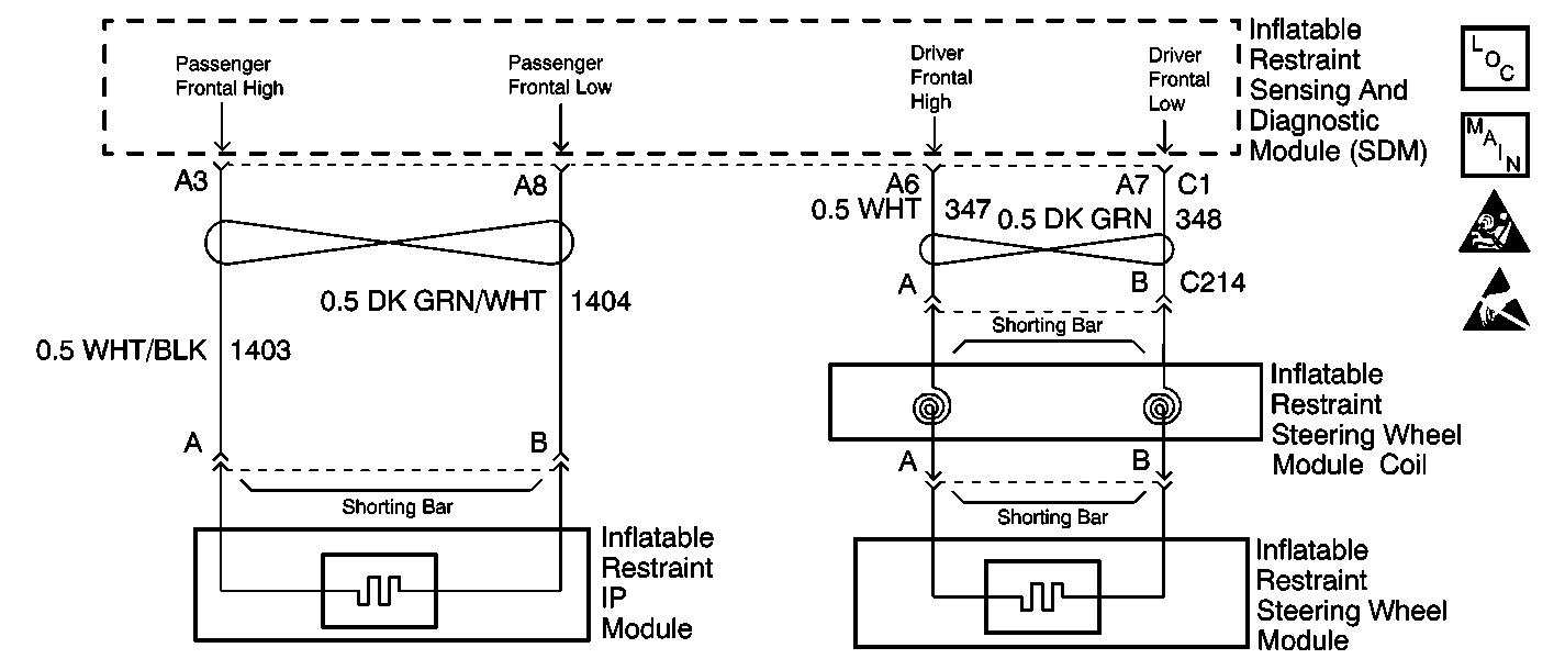
Circuit Description
The driver frontal air bag deployment loop is a 2 wire circuit. One wire is the high side of the loop while the other is the low side of the loop. When you first turn the ignition switch ON, the inflatable restraint sensing and diagnostic module (SDM) performs tests to diagnose critical malfunctions within itself. Then the SDM performs the following continuous diagnostic tests on the deployment loops:
| • | Deployment loop voltage out of range test |
| • | Deployment loop resistance measurement test |
If the voltage out of range test detects a short to voltage condition, the resistance measurement test for that deployment loop will not be performed.
Conditions for Running the DTC
The SDM monitors the driver frontal air bag deployment loop at power on and continuously there after.
Conditions for Setting the DTC
| • | Ignition 1 voltage is within the normal operating voltage range. |
| • | Driver frontal deployment loop is not open. |
| • | Driver frontal deployment loop is not shorted to voltage. |
| • | Driver frontal deployment loop is not shorted to ground. |
| • | Driver frontal deployment loop resistance is less than 1.3 ohms for 5 consecutive samples, the SDM sets this code. |
The driver frontal deployment loop consists of the following components:
| • | Inflatable restraint steering wheel module. |
| • | Inflatable restraint steering wheel module coil. |
| • | Harness wiring of driver frontal high and low deployment circuits. |
| • | Connector terminal contact. |
This malfunction is detected during the deployment loop resistance measurement test.
Action Taken When the DTC Sets
| • | The SDM sets a DTC. |
| • | The SDM commands AIR BAG warning lamp ON through a Class 2 message to the cluster (IP). |
The SDM also sets this DTC as current after an accident. The SDM will write the status of this DTC to the "crash log" area of the EEPROM for retrieval.
Conditions for Clearing the DTC
| • | Current DTC |
| The resistance of the driver frontal deployment loop is greater than or equal to 1.3 ohms for 5 consecutive samples. |
| • | CLEAR CODES command. |
| • | History DTC |
| - | You issue a scan tool CLEAR CODES command. |
| - | Once 255 malfunction free ignition cycles have occurred. |
| • | When the SDM detect that no DTCs are present, the SDM commands the AIR BAG warning lamp to be turn OFF. |
Diagnostic Aids
If the DTC is stored as a history DTC the deployment circuit must be checked for:
| • | Frayed insulation |
| • | Damaged connectors |
| • | Moisture damage |
| • | Stretched/broken wires |
The fact that the DTC set and is now stored as a history DTC indicates a short between the two sides of the deployment circuit has happened in the past. The short will prevent deployment if it happens again during a commanded air bag deployment.
Test Description
The number(s) below refer to the step number(s) on the diagnostic table.
-
This step checks the in-line connector below the steering wheel restraint module coil.
-
This step test for the proper operation of inflatable restraint steering wheel module coil and/or inflatable restraint steering wheel inflator module.
-
This step determines if there is a short between driver frontal high and driver frontal low circuits, or if there is a malfunctioning SDM.
Step | Action | Value(s) | Yes | No | ||||||||
|---|---|---|---|---|---|---|---|---|---|---|---|---|
1 | Did you perform the A Diagnostic System Check-SIR? | -- | ||||||||||
Does connector exhibits any signs of corrosion, terminal damaged, or poor connections? | -- | |||||||||||
3 |
Did you complete the replacement? | -- | -- | |||||||||
4 |
Does the scan tool indicate that this DTC is current? | -- | Go to Diagnostic Aids | |||||||||
5 |
Does the scan tool indicate that this DTC is current? | -- | ||||||||||
Does the scan tool indicate that this DTC is current? | -- | |||||||||||
7 |
Did you complete the replacement? | -- | -- | |||||||||
8 |
Did you complete the replacement? | -- | -- | |||||||||
Does the resistance measure less than the specified value? | OL | |||||||||||
10 | Locate and repair a short between the driver frontal high and the driver frontal low deployment circuits of the SDM wiring harness connector. Refer to Circuit Testing and Wiring Repairs in Wiring Systems. Did you complete the repair? | -- | -- | |||||||||
11 | Replace the SDM. Refer to Inflatable Restraint Sensing and Diagnostic Module Replacement . Did you complete the replacement? | -- | -- | |||||||||
12 |
Did you complete the action? | -- | -- |
