Circuit Description
The powertrain control module (PCM) controls the air entering into the engine with an idle control (IAC) valve. In order to increase the idle RPM, the PCM commands the pintle inside the IAC valve away from the throttle body seat. This allows more air to bypass through the throttle blade. In order to decrease the RPM the PCM commands the pintle towards the throttle body seat. This reduces the amount of air bypassing the throttle blade. A scan tool will read the IAC valve pintle position in counts. The higher the counts, the more air that is allowed to bypass the throttle blade.
Conditions for Running the DTC
| • | DTCs P0105, P0107, P0108, P0112, P0113, P0117, P0118, P0122, P0123, P0125, P0131, P0132, P0133, P0134, P0200, P0335, P0341, P0342, P0440, P0442, P0446, P0480, P0502, P0503, P0601, P0602, P1133, and P1441 not set |
| • | BARO is more than 72 kPa. |
| • | Engine coolant temperature (ECT) is more than 40°C (104°F). |
| • | Engine has been running more than 20 seconds. |
| • | Throttle position (TP) angle is less than 1 percent. |
Conditions for Setting the DTC
| • | The idle speed deviates above desired RPM by more than 60 RPM for more than 5 seconds. |
| • | The IAC valve reads less than 2 counts on the scan tool. |
Action Taken When the DTC Sets
| • | The control module illuminates the malfunction indicator lamp (MIL) if a failure is detected during 2 consecutive key cycles. |
| • | The control module sets the DTC and records the operating conditions at the time the diagnostic failed. The failure information is stored in the scan tools Freeze Frame and Failure Records. |
Conditions for Clearing the MIL/DTC
| • | The control module turns OFF the MIL after 3 consecutive drive trips when the test has Run and Passed |
| • | A history DTC will clear if no fault conditions have been detected for 40 warm-up cycles. A warm up cycle occurs when the coolant temperature has risen 22°C (40°F) from the startup coolant temperature and the engine coolant reaches a temperature that is more than 70°C (158°F) during the same ignition cycle. |
| • | Use a scan tool to clear the DTCs. |
Diagnostic Aids
| • | Inspect the IAC valve electrical connection for proper mating. |
| • | Inspect the wiring harness for damage. |
| • | Inspect for a disconnected, cracked or cut vacuum hoses. |
| • | Inspect for the proper installation of the crankcase ventilation valve. |
| • | Inspect the intake manifold and throttle body for leaks. |
| • | Inspect the intake manifold for cracks. |
| • | Refer to Rough, Unstable, or Incorrect Idle and Stalling . |
Test Description
The numbers below refer to the step numbers on the diagnostic table.
-
A normally operating IAC system will be able to extend and retract by a scan tool and change the engine idle RPM. The valve movement is verified by an engine RPM change.
-
If the scan tool was able to command the IAC valve smoothly, a malfunction may still exist internally within the IAC valve. Verify this by checking the internal resistance of the IAC valve.
-
The IAC circuits always have ground or voltage signals in pairs. If the test lamp illuminates on more or less than two terminals, one of the circuits is shorted to voltage or open.
-
The IAC circuits always have ground or voltage signals in pairs. If the test lamp illuminates on more or less than two terminals, one of the circuits is shorted to ground or open.
-
The IAC circuits are constantly switched between ground and voltage. The test lamp should blink on all circuits when connected to a ground.
-
A test lamp that remains ON constantly indicates that the circuit is shorted to voltage.
-
Thoroughly inspect any suspected circuitry for the following conditions:
-
The replacement PCM must be programmed, and the Crankshaft Position System Variation Learn procedure must be performed.
-
If no malfunctions are present at this point and no additional DTCs were set, refer to Diagnostic Aids for additional checks and information.
| • | Backed-out terminals |
| • | Improper mating |
| • | Broken locks |
| • | Improperly formed or damaged terminals |
| • | Faulty terminal-to wire connections |
| • | Physical damage to the wiring harness |
Step | Action | Value(s) | Yes | No | ||||||
|---|---|---|---|---|---|---|---|---|---|---|
1 | Did you perform the Powertrain On-Board Diagnostic (OBD) System Check? | -- | ||||||||
Does the engine RPM change smoothly when commanded by the scan tool? | 900-2,000 RPM | |||||||||
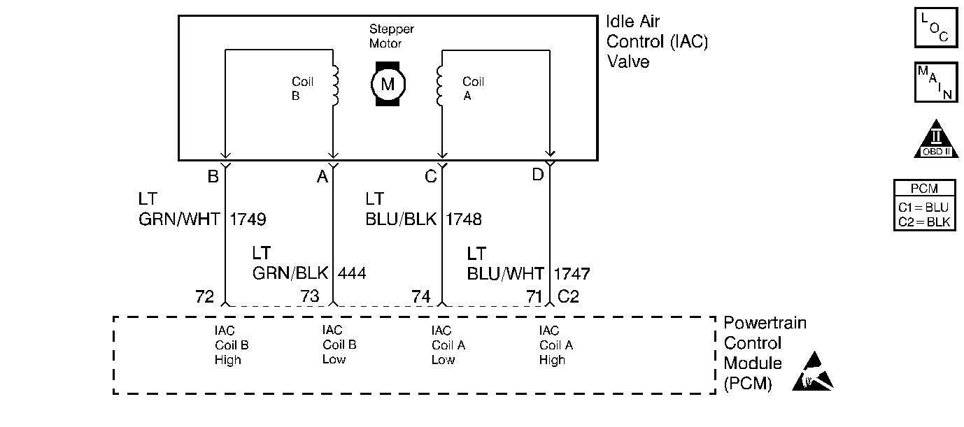
Are the resistances across terminals A and B, C and D within the specified value? | 40-80 ohms | |||||||||
4 |
Are the resistances across terminals B and C and terminals A and D infinite? | -- | ||||||||
Does the test lamp illuminate on 2 terminals? | -- | |||||||||
Does the test lamp illuminate on 2 terminals? | -- | |||||||||
Does the test lamp flash ON and OFF for all of the terminals? | -- | |||||||||
Did the test lamp remain ON constantly for the terminals that did not blink? | -- | |||||||||
9 |
Did you find and correct the condition? | -- | ||||||||
10 |
Did you find and correct the condition? | -- | ||||||||
Did you find and complete the repair? | -- | |||||||||
12 |
Did you find and correct the condition? | -- | ||||||||
13 |
Did you find and correct the condition? | -- | ||||||||
14 | Replace the IAC valve. Refer to the Idle Air Control Valve Replacement . Did you complete the replacement? | -- | -- | |||||||
|
Important:: The replacement PCM must be programmed. Replace the PCM. Refer to Powertrain Control Module Replacement/Programming . Did you complete the replacement? | -- | -- | ||||||||
16 |
Does the scan tool indicate that this diagnostic has run and passed? | -- | ||||||||
Check to see if any additional DTCs are set. Does the scan tool display any DTCs that you have not diagnosed? | System OK |
