Important: A control module refers to the PCM and the VCM.
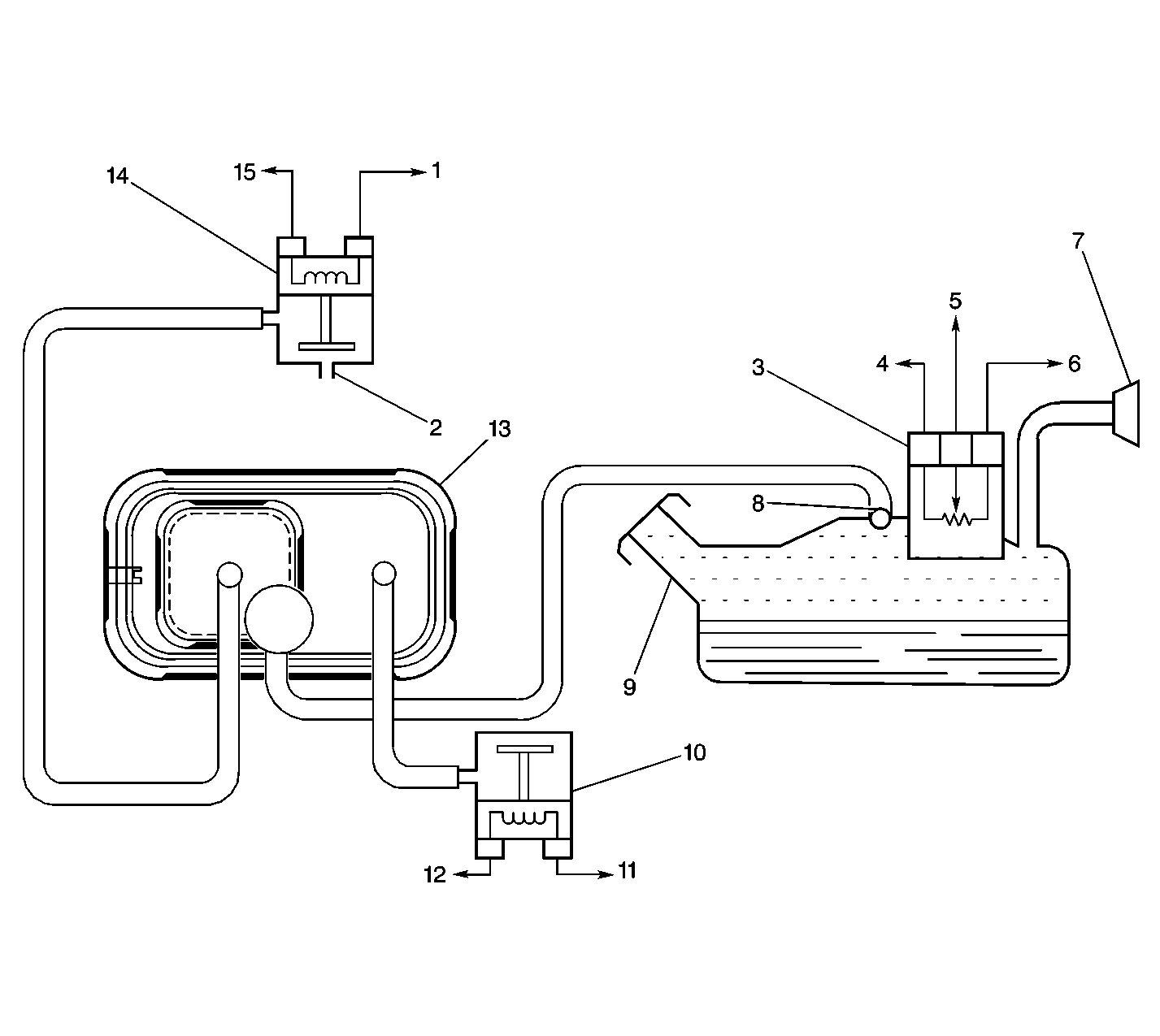
The evaporative emission (EVAP) control system limits the fuel vapors escaping into the atmosphere. The EVAP transfers fuel vapor from the sealed fuel tank to an activated carbon (charcoal) storage device called the EVAP canister. The EVAP canister stores the vapors until the engine is able to use the extra fuel vapor.
When the engine is able to use the extra fuel vapor, the intake air flow purges the fuel vapor from the carbon element, and the vapor is then consumed in the normal combustion process.
The EVAP control system can detect evaporative fuel system leaks as small as 0.040 between the fuel filler cap and the purge solenoid. The EVAP control system tests the evaporative system's integrity by applying a vacuum signal (ported or manifold) to the fuel tank in order to create a small vacuum.
The EVAP control module monitors the ability of the EVAP system to maintain the vacuum. If the vacuum remains for a specified period of time, then there are no evaporative leaks, and a PASS report is sent to the control module. If there is a leak, the system either will not achieve a vacuum, or a vacuum will not be maintained. Usually a fault can only be detected after a cold start with a trip of sufficient length and the appropriate driving conditions to run the needed tests. The enhanced evaporative system diagnostic conducts up to 8 specific sub-tests in order to detect the fault conditions. If the diagnostic fails a sub-test, the control module stores a diagnostic trouble code (DTC) indicating the type of fault detected.