Product Safety 99041 - Incorrect Front Axle Status Signal to EBC4 ABS

| Subject: | 99041 -- Incorrect Front Axle Status Signal to EBC4 ABS |
| Models: | 1991-1996 Chevrolet and GMC 4WD T Utilities |
| 1994-1996 Chevrolet and GMC 4WD T Pickup Trucks |
| Attention: | DUE TO THE AVAILABILITY OF PARTS, THIS CAMPAIGN WILL BE ADMINISTERED IN PHASES. YOU WILL RECEIVE A DEALER LISTING AS PHASES ARE RELEASED. |
Condition
General Motors has decided that a defect which relates to motor vehicle safety exists in certain 1991-1996 Chevrolet and GMC 4WD T utilities and 1994-1996 Chevrolet and GMC 4WD T pickup trucks. Some of these vehicles exhibit a condition in which a switch that signals the antilock brake system (ABS) module when the vehicle is in four-wheel drive (4WD) may malfunction. The ABS module is designed with two different operating algorithms: one for two-wheel drive (2WD) operation and another for 4WD operation. This allows the ABS system to compensate for the braking torque applied to the rear wheels through the drivetrain when the vehicle is in 4WD drive. When the vehicle is in 2WD, a malfunctioning switch may send an incorrect signal to the ABS module. If this occurs during an ABS stop, a somewhat longer stopping distance could result. If this occurred when minimum stopping distance was required, it could result in a vehicle crash.
Correction
Dealers are to install a new transfer case selector switch, wiring harness, and an additional switch to ensure that the ABS receives the 4WD signal only when the drivetrain is in 4WD.
Vehicles Involved
Involved are certain 1991-1996 Chevrolet and GMC 4WD T utilities and 1994-1996 Chevrolet and GMC 4WD T pickup trucks built within these VIN breakpoints:
Year | Division | Model | Plant | From | Through |
|---|---|---|---|---|---|
1991 | GMC | T Utility | Moraine | M2500005 | M2561399 |
1992 | GMC | T Utility | Moraine | N2500001 | N2539169 |
1992 | GMC | T Utility | Shreveport | N8500002 | N8500002 |
1992 | GMC | T Utility | Pontiac West | N0500002 | N0519368 |
1993 | GMC | T Utility | Moraine | P2500002 | P2543249 |
1993 | GMC | T Utility | Pontiac West | P0500007 | P0528015 |
1994 | GMC | T Utility | Moraine | R2500002 | R2527917 |
1994 | GMC | T Utility | Pontiac West | R0500001 | R0535325 |
1995 | GMC | T Utility | Moraine | S2500001 | S2559899 |
1995 | GMC | T Utility | Linden | SK500001 | SK545839 |
1996 | GMC | T Utility | Moraine | T2500001 | T2580013 |
1996 | GMC | T Utility | Linden | TK500001 | TK532448 |
1994 | GMC | T Pickup | Shreveport | R8500040 | R85533971 |
1994 | GMC | T Pickup | Linden | RK500006 | RK525917 |
1995 | GMC | T Pickup | Shreveport | S8500003 | S9541052 |
1995 | GMC | T Pickup | Linden | SK500022 | SK545837 |
1996 | GMC | T Pickup | Shreveport | T8500001 | T8536519 |
1996 | GMC | T Pickup | Linden | TK500013 | TK531877 |
1991 | Chevrolet | T Utility | Moraine | M2100006 | M2325893 |
1992 | Chevrolet | T Utility | Moraine | N2100002 | N2226379 |
1992 | Chevrolet | T Utility | Shreveport | N8100004 | N8100010 |
1992 | Chevrolet | T Utility | Pontiac West | N0100004 | N0161853 |
1993 | Chevrolet | T Utility | Moraine | P2100001 | P2218436 |
1993 | Chevrolet | T Utility | Pontiac West | P0100002 | P0196997 |
1994 | Chevrolet | T Utility | Moraine | R2100002 | R2179415 |
1994 | Chevrolet | T Utility | Pontiac West | R0100001 | R0184857 |
1995 | Chevrolet | T Utility | Moraine | S2100001 | S2266694 |
1995 | Chevrolet | T Utility | Linden | SK100004 | SK263006 |
1996 | Chevrolet | T Utility | Moraine | T2100004 | T2318776 |
1996 | Chevrolet | T Utility | Linden | TK100006 | TK240985 |
1994 | Chevrolet | T Pickup | Shreveport | R8100011 | R8243089 |
1994 | Chevrolet | T Pickup | Linden | RK100001 | RK183770 |
1995 | Chevrolet | T Pickup | Shreveport | S8100002 | S8266172 |
1995 | Chevrolet | T Pickup | Linden | SK100038 | SK262978 |
1996 | Chevrolet | T Pickup | Shreveport | T8100002 | T8232042 |
1996 | Chevrolet | T Pickup | Linden | TK100019 | TK239494 |
Important: Dealers should confirm vehicle eligibility through GMVIS (GM Vehicle Inquiry System) or GM Access Screen (Canada only) or DCS Screen 445 (IPC Only) before beginning campaign repairs. [Not all vehicles within the above breakpoints may be involved.]
Involved vehicles have been identified by Vehicle Identification Number. Computer listings containing the complete Vehicle Identification Number, customer name and address data have been prepared, and are being furnished to involved dealers with the campaign bulletin. The customer name and address data furnished will enable dealers to follow-up with customers involved in this campaign. Any dealer not receiving a computer listing with the campaign bulletin has no involved vehicles currently assigned.
These dealer listings may contain customer names and addresses obtained from Motor Vehicle Registration Records. The use of such motor vehicle registration data for any other purpose is a violation of law in several states/provinces/countries. Accordingly, you are urged to limit the use of this listing to the follow-up necessary to complete this campaign.
Parts Information
Parts required to complete this campaign are to be obtained from General Motors Service Parts Operations (GMSPO). Please refer to your "involved vehicles listing" before ordering parts. Normal orders should be placed on a DRO=Daily Replenishment Order. In an emergency situation, parts should be ordered on a CSO=Customer Special Order.
Part Number | Description | Qty/ Vehicle |
|---|---|---|
88880028 | Switch Kit, Elek Brk Cont Frt Drv Axle Vac (1991-94 Utility) | 1 |
88880029 | Switch Kit, Elek Brk Cont Frt Drv Axle Vac (1995-96 Utility, 1994-96 Pickup) | 1 |
Service Procedure
1991-94 T Utility
- Disconnect the negative battery cable.
- Remove the front lower coolant reservoir attaching bolt.
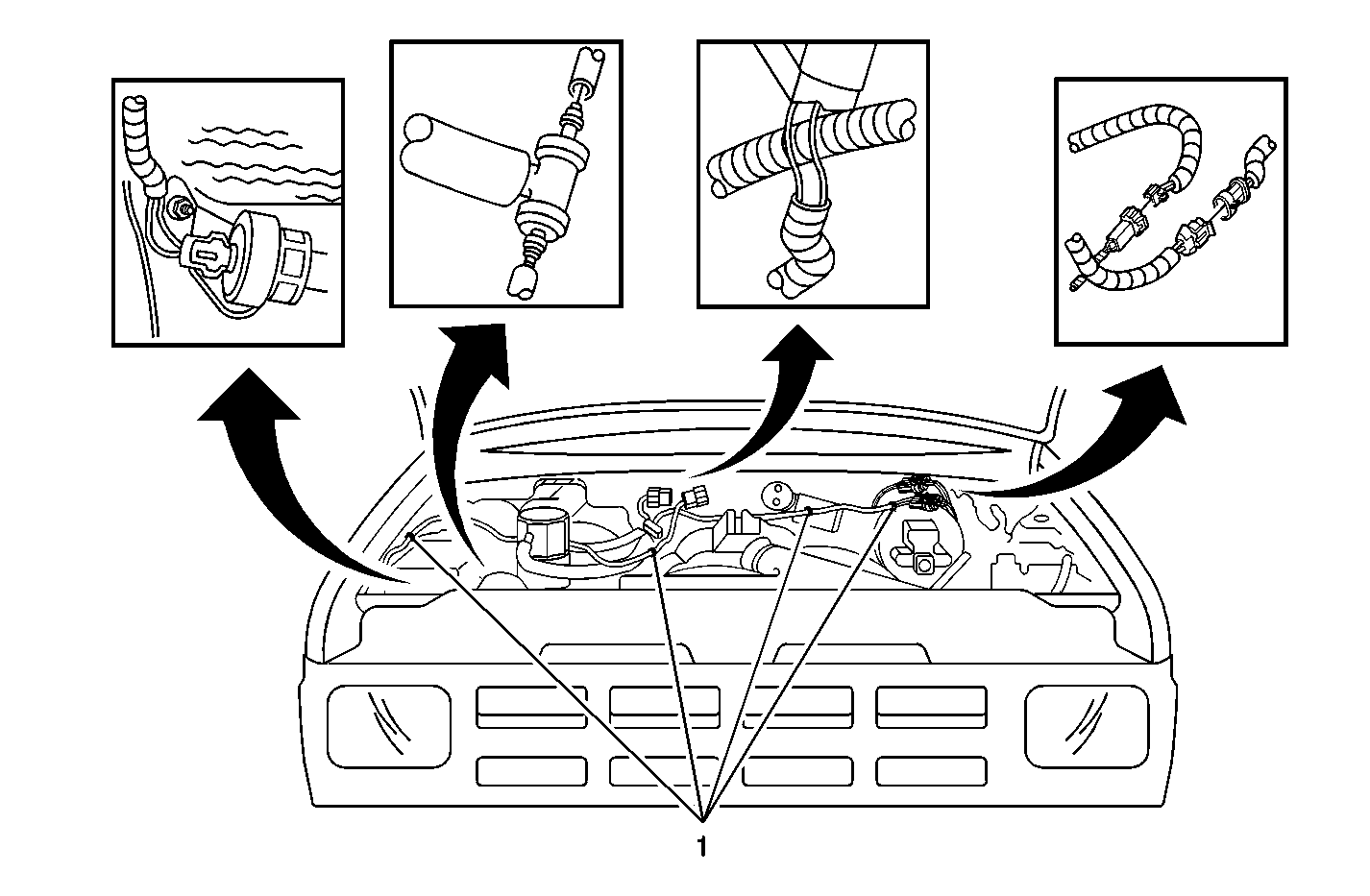
- Install the new vacuum switch, the bracket and the hose assembly at the front lower coolant reservoir attaching location using the bolt removed in the previous step.
Figure 1

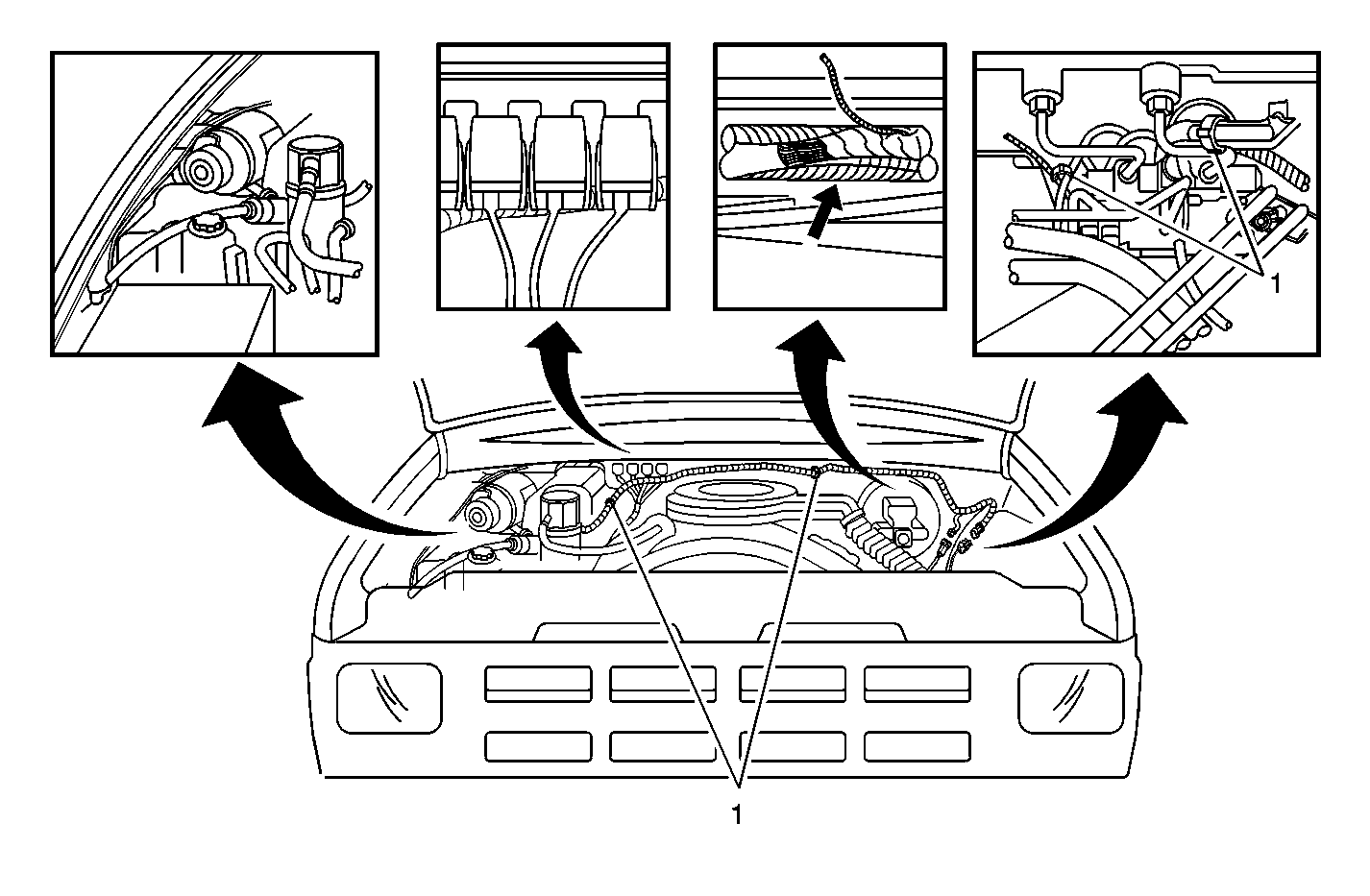
1994 T Pickup
- Disconnect the negative battery cable.
Figure 2

1995-96 T Pickup and 1995-96 T Utility
- Disconnect the negative battery cable.
- Remove the front lower coolant reservoir attaching nut. Discard the nut.
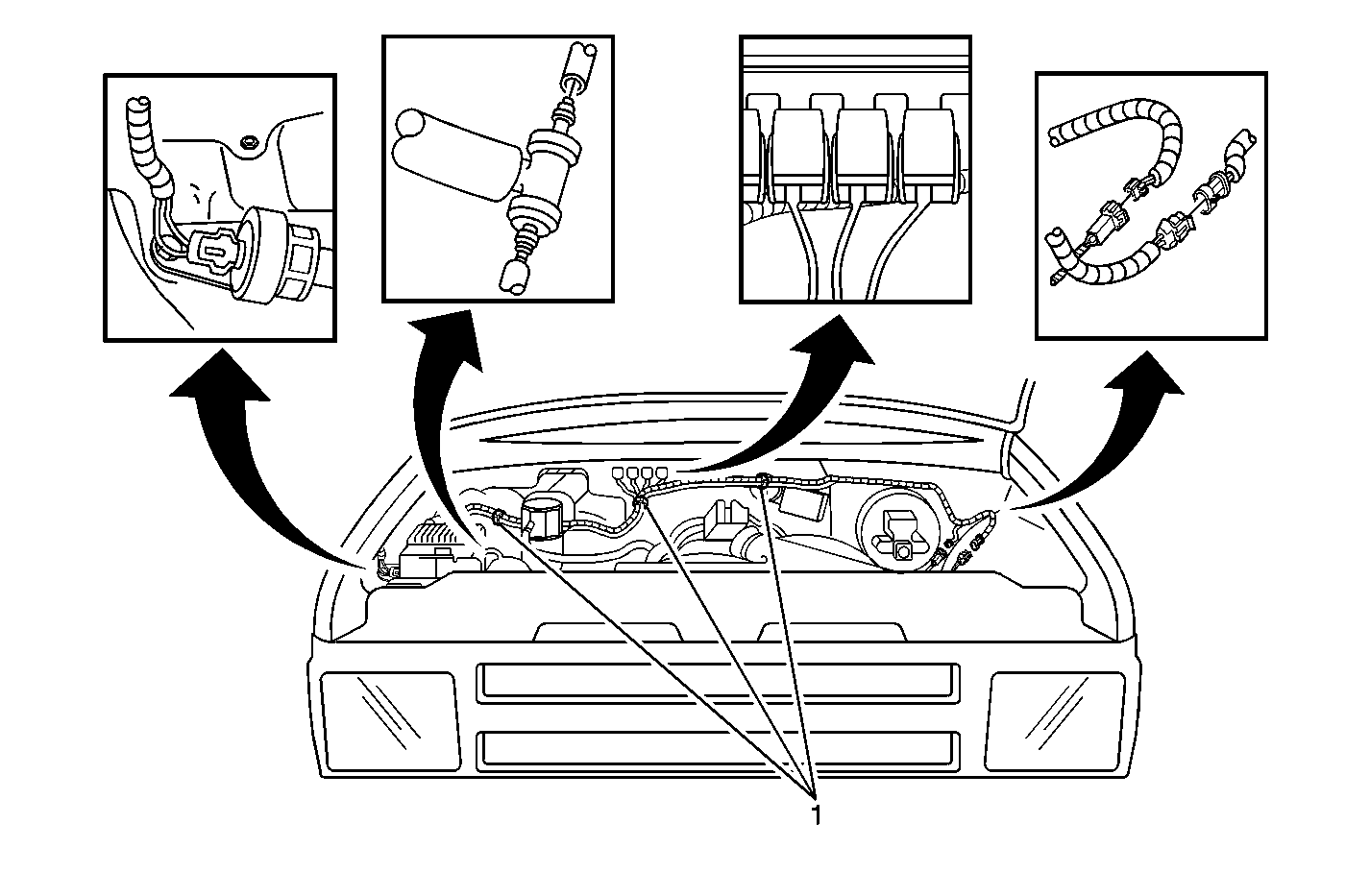
- Install the new vacuum switch, the bracket, and the hose assembly at the front lower coolant reservoir attaching location using the new nut contained in the kit.
Figure 3

Campaign Identification Label
FOR US AND IPC
Place a Campaign Identification Label on each vehicle corrected in accordance with the instructions outlined in this Product Campaign Bulletin. Each label provides a space to include the campaign number and the five (5) digit dealer code of the dealer performing the campaign service. This information may be inserted with a typewriter or a ball point pen.
Put the Campaign Identification Label on a clean and dry surface of the radiator core support in an area that will be visible to people servicing the vehicle. When installing the Campaign Identification Label, be sure to pull the tab to allow the adhesion of the clear protective covering. Additional Campaign Identification Labels for US dealers can be obtained from Dealer Support Material by calling 1-888-549-6152 (Monday-Friday, 8:00 am to 5:00 pm EST). Ask for Item Number S-1015 when ordering.
Additional Campaign Identification Labels for IPC dealers can be obtained from your Regional Marketing Office.
Campaign Identification Label
FOR CANADA
Place a Campaign Identification Label on each vehicle corrected in accordance with the instructions outlined in this Product Campaign Bulletin. Each label provides a space to include the campaign number and the five (5) digit dealer code of the dealer performing the campaign service. This information may be inserted with a typewriter or a ball point pen.
Put the Campaign Identification Label on a clean and dry surface of the radiator core support in an area that will be visible to people servicing the vehicle. Additional Campaign Identification Labels for Canadian dealers can be obtained from DGN by calling 1-800-668-5539 (Monday-Friday, 8:00 am to 5:00 pm EST). Ask for Item Number GMP 91 when ordering.
Claim Information
Submit a Product Campaign Claim with the information indicated below:
Repair Performed | Part Count | Part No. | Parts Allow | CC-FC | Labor Op | Labor Hours* |
|---|---|---|---|---|---|---|
Install New Vacuum Switch, Wiring Harness & Transfer Case Selector Switch | 1 | -- | ** | MA-96 | V0358 | 0.5 |
* -- For Campaign Administrative Allowance, add 0.1 hours to the "Labor Hours". ** -- The "Parts Allowance" should be the sum total of the current GMSPO Dealer Net price plus applicable Mark-Up or Landed Cost Mark-Up (for IPC) for the switch kit needed to complete the repair. | ||||||
Refer to the General Motors WINS Claims Processing Manual for details on Product Campaign Claim Submission.
Customer Notification
FOR US AND CANADA
Customers will be notified of this campaign on their vehicles by General Motors (see copy of customer letter included with this bulletin).
Customer Notification
FOR IPC
Letters will be sent to known owners of record located within areas covered by the US National Traffic and Motor Vehicle Safety Act. For owners outside these areas, dealers should notify customers using the attached suggested dealer letter.
Dealer Campaign Responsibility
FOR US AND IPC (US States, Territories, and Possessions)
The US National Traffic and Motor Vehicle Safety Act provides that each vehicle which is subject to a recall campaign of this type must be adequately repaired within a reasonable time after the customer has tendered it for repair. A failure to repair within sixty days after tender of a vehicle is prima facie evidence of failure to repair within a reasonable time.
If the condition is not adequately repaired within a reasonable time, the customer may be entitled to an identical or reasonably equivalent vehicle at no charge or to a refund of the purchase price less a reasonable allowance for depreciation.
To avoid having to provide these burdensome remedies, every effort must be made to promptly schedule an appointment with each customer and to repair their vehicle as soon as possible. In the recall campaign notification letters, customers are told how to contact the US National Highway Traffic Safety Administration if the campaign is not completed within a reasonable time.
Dealer Campaign Responsibility
FOR ALL
All unsold new vehicles in dealers' possession and subject to this campaign MUST be held and inspected/repaired per the service procedure of this campaign bulletin BEFORE customers take possession of these vehicles.
Dealers are to service all vehicles subject to this campaign at no charge to customers, regardless of mileage, age of vehicle, or ownership, from this time forward.
Customers who have recently purchased vehicles sold from your vehicle inventory, and for which there is no customer information indicated on the dealer listing, are to be contacted by the dealer. Arrangements are to be made to make the required correction according to the instructions contained in this bulletin. This could be done by mailing to such customers a copy of the customer letter accompanying this bulletin. Campaign follow-up cards should not be used for this purpose, since the customer may not as yet have received the notification letter.
In summary, whenever a vehicle subject to this campaign enters your vehicle inventory, or is in your dealership for service in the future, please take the steps necessary to be sure the campaign correction has been made before selling or releasing the vehicle.
Suggested Dealer Letter
General Motors has decided that a defect which relates to motor vehicle safety exists in certain 1991-1996 4-wheel drive (4WD) Blazers and Jimmys, and 1994-1996 4WD S10 and Sonoma pickup trucks. Some of these vehicles exhibit a condition in which a switch that signals the antilock brake system (ABS) module when the vehicle is in 4WD may malfunction. The ABS module is designed with two different operating algorithms: one for two-wheel drive (2WD) operation and another for 4WD drive operation. This allows the ABS system to compensate for the braking torque applied to the rear wheels through the drivetrain when the vehicle is in 4WD drive. When the vehicle is in 2WD, a malfunctioning switch may send an incorrect signal to the ABS module. If this occurs during an ABS stop, a somewhat longer stopping distance could result. If this occurred when minimum stopping distance was required, it could result in a vehicle crash.
Your dealer will install a new transfer case selector switch, wiring harness, and an additional switch to ensure that the ABS receives the 4WD signal only when the drivetrain is in 4WD. This service will be performed for you at no charge .
This service will be performed for you at no charge.
Please contact us as soon as possible to arrange a service date.
We sincerely regret any inconvenience this causes you; however, we have taken this action in the interest of your continued satisfaction with our products.
GMODC
General Motors Corporation
May, 2000Dear General Motors Customer:
This notice is sent to you in accordance with the requirements of the National Traffic and Motor Vehicle Safety Act.
Reason For This Recall
General Motors has decided that a defect which relates to motor vehicle safety exists in certain 1991-1996 Chevrolet and GMC 4WD T utilities and 1994-1996 Chevrolet and GMC 4WD T pickup trucks. Some of these vehicles exhibit a condition in which a switch that signals the antilock brake system (ABS) module when the vehicle is in four-wheel drive (4WD) may malfunction. The ABS module is designed with two different operating algorithms: one for two-wheel drive (2WD) operation and another for 4WD operation. This allows the ABS system to compensate for the braking torque applied to the rear wheels through the drivetrain when the vehicle is in 4WD drive. When the vehicle is in 2WD, a malfunctioning switch may send an incorrect signal to the ABS module. If this occurs during an ABS stop, a somewhat longer stopping distance could result. If this occurred when minimum stopping distance was required, it could result in a vehicle crash.
What Will Be Done
Your dealer will install a new transfer case selector switch, wiring harness and an additional switch to ensure that the ABS receives the 4WD signal only when the drivetrain is in 4WD. This service will be performed for you at no charge .
How Long Will The Repair Take?
The length of time required to perform this service correction is approximately 30 minutes. Additional time may be required to schedule and process your vehicle. If you dealer has a large number of vehicles awaiting service, this additional time may be significant. Please ask your dealer if you wish to know how much additional time will be needed to schedule, process and repair your vehicle.
Contacting Your Dealer
Please contact your Chevrolet/GMC dealer as soon as possible to arrange a service date. Parts are available and instructions for making this correction have been sent to your dealer.
Your Chevrolet/GMC dealer is best equipped to obtain parts and provide services to correct your vehicle as promptly as possible. Should your dealer be unable to schedule a service date within a reasonable time, you should contact the appropriate Customer Assistance/Relations Center at the number listed below:
Division | Number | Deaf, Hearing Impaired, or Speech Impaired* |
|---|---|---|
Chevrolet | 1-800-222-1020 | 1-800-833-2438 |
GMC | 1-800-462-8782 | 1-800-462-8583 |
* Utilizes Telecommunication Devices for the Deaf/Text Telephones (TDD/TTY) | ||
If, after contacting the appropriate customer assistance center, you are still not satisfied that we have done our best to remedy this condition without charge and within a reasonable time, you may wish to write the Administrator, National Highway Traffic Safety Administration, 400 Seventh Street SW, Washington, DC 20590 or call 1-800-424-9393 (Washington, DC residents use 202-366-0123).
Customer Reply Card
The attached customer reply card identifies your vehicle. Presentation of this card to your dealer will assist in making the necessary correction in the shortest possible time. If you no longer own this vehicle, please let us know by completing the attached and mailing it in the postage paid envelope.
We are sorry to cause you this inconvenience; however, we have taken this action in the interest of your safety and continued satisfaction with our products.
Chevrolet/Pontiac-GMC Division
General Motors Corporation
Enclosure
