TRANSFER CASE HOPOUT FROM 4 HIGH TO 2 HIGH/REPAIR

Model and Year: 1988-89 T TRUCKS WITH 231 TRANSFER CASE
Some 1988-89 T trucks may experience transfer case "hopout" from four-wheel drive high range to two-wheel drive mode. This condition is most prevalent under extreme cold weather conditions (below 0 degrees F).
Some probable causes are listed below:
1. Transfer case not fully engaged into 4-High position.
2. Transfer case boot convolute trapped beneath the floor console.
3. Transfer case shift linkage (detent bracket) improperly adjusted.
4. Inadequate transfer case detent spring load.
Service Procedure:
Check to assure that the transfer case is fully engaged into the 4-High position. If hopout occurs, perform the following service procedure:
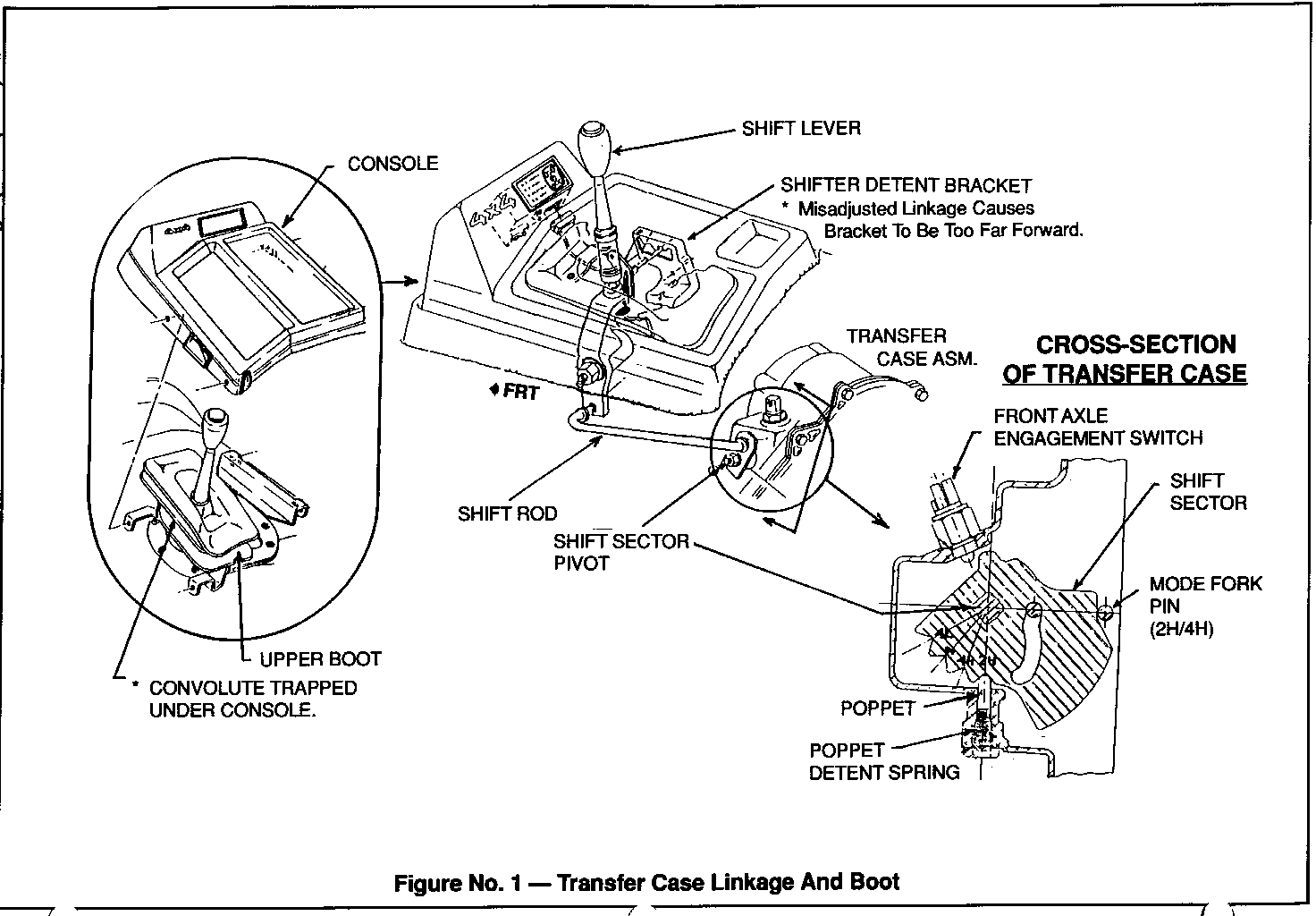
1. Inspect the transfer case upper boot and verify that the lower convolute is not trapped beneath the console (Figure 1). Correct the boot installation as required.
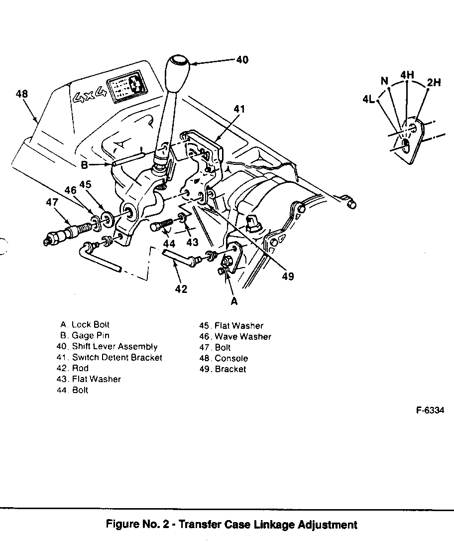
2. Inspect the transfer case shift linkage (Figure 1). Use the following procedure to properly adjust the transfer case shift linkage (See Figure 2).
A. Remove the console (48).
B. Raise the shift lever boot up the shift lever.
C. Loosen bolt (44).
D. Loosen bolt (47).
E. Place the shift lever (40) in 4-High position.
F. Install a suitable bolt (A) at the shift lever on the transfer case as shown. This will lock the transfer case in 4-High.
G. Insert an 8 mm (5/16-inch) diameter gage pin or drill bit through the hole in the shift lever into the upper corner of the switch detent bracket (49). This aligns the switch assembly in the 4-High position.
H. Tighten bolt (47) to 130 N.m (95 lbs/ft).
I. Tighten bolt (44) to 40 N.m (30 lbs/ft).
J. Remove the lock bolt (A) and gage pin or drill bit (B).
K. Install the console and boot.
Check for proper illumination of the display indicator when in each shift position. When properly adjusted, and in the 4-High position, the shift lever should have approximately 2-4 mm of rearward play at the knob before hitting the 4-High detent stop.
IMPORTANT:Do not depress the detent button when checking rearward play.
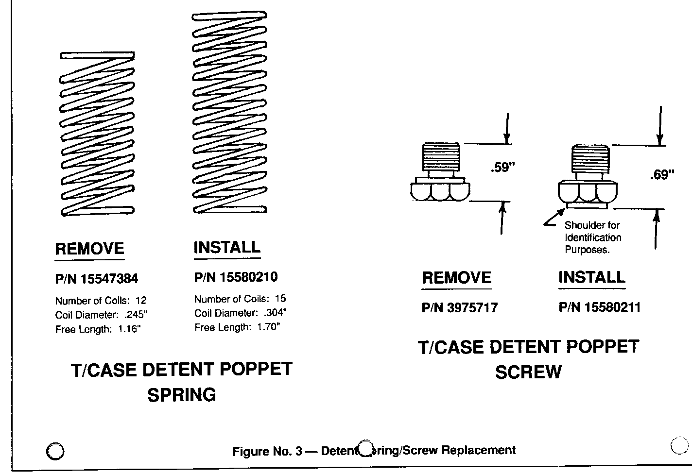
3. Replace the transfer case detent poppet spring (P/N 15547384) with P/N 15580210. Replace the transfer case detent spring retaining screw (P/N 3975717) with P/N 15580211. This will increase the detent spring load (Figure 3).
Parts are currently available from GMSPO.
NOTICE: Both the detent poppet spring and detent poppet screw must be replaced together. Interchanging the old and new parts may cause shifting problems (i.e. an inability to shift the transfer case).
Transfer case oil must be drained to perform the above part change. Refill with Dexron II upon completion.
Date of Production Change:
Vehicles in which the new detent poppet spring and poppet screw have been incorporated can be identified in two ways. First, the new screw is designed with a shoulder on the face (See Figure 3). Second, the transfer cases with build dates after 3/16/89 will have the new spring and screw installed. The build date is located on the transfer case I.D. tag as the serial number i.e. 5-26 88-1 is May 26, 1988, 1st shift. The I.D. tag is red.
Labor Operation Number: T7950
Labor Time: .9 Hr
General Motors bulletins are intended for use by professional technicians, not a "do-it-yourselfer". They are written to inform those technicians of conditions that may occur on some vehicles, or to provide information that could assist in the proper service of a vehicle. Properly trained technicians have the equipment, tools, safety instructions and know-how to do a job properly and safely. If a condition is described, do not assume that the bulletin applies to your vehicle, or that your vehicle will have that condition. See a General Motors dealer servicing your brand of General Motors vehicle for information on whether your vehicle may benefit from the information.
