Tools Required
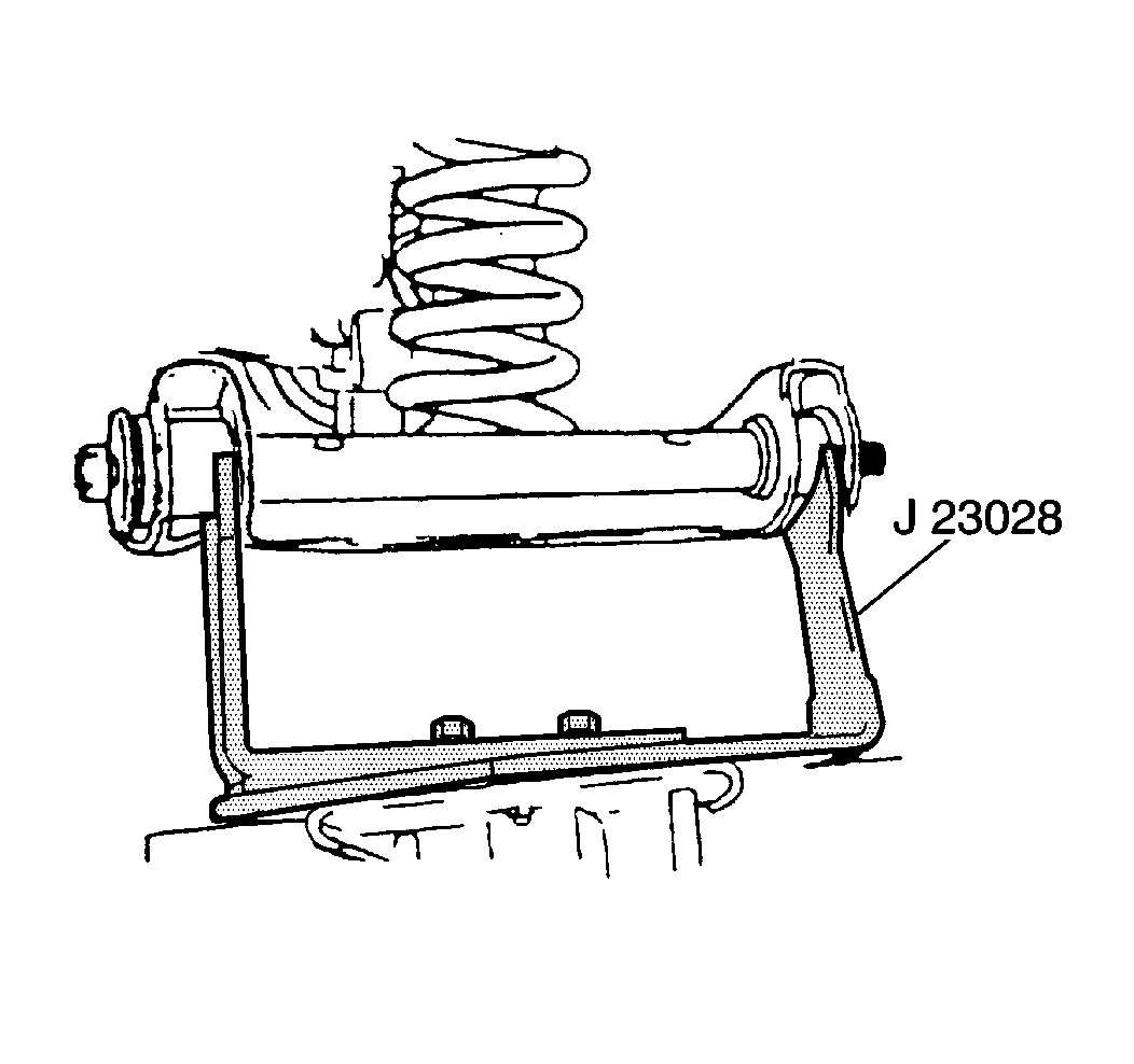
J 23028-A Coil Spring Remover and Installer
Removal Procedure
- Remove the stabilizer shaft link from the lower control arm. Refer to Stabilizer Shaft Link Replacement .
- Remove the shock absorber. Refer to Shock Absorber Replacement .
- Secure J 23028-A to the end of a suitable jack.
- Cradle the lower control arm bushings using J 23028-A .
- Raise the jack in order to relieve tension on the lower control arm pivot bolts.
- Turn the steering wheel to one side in order to allow the steering linkage to clear the lower control arm front pivot bolt.
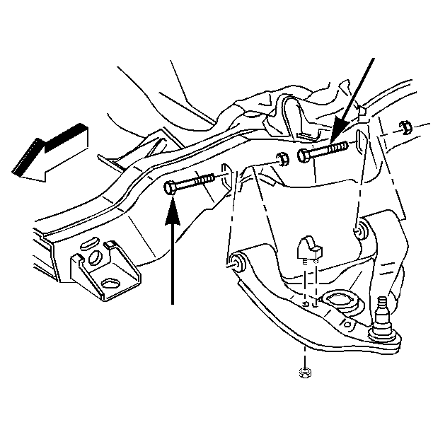
- Remove the lower control arm pivot bolts and nuts.
- Lower J 23028-A slowly to relieve the tension from the front coil spring.
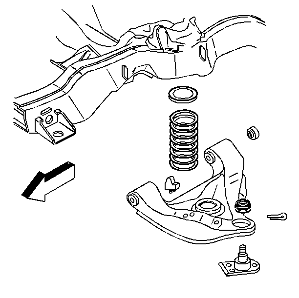
- Remove the front coil spring and the insulators. While removing the front coil spring, do not apply force to the lower control arm and/or lower ball joint.
Notice: Use care when handling the coil springs in order to avoid chipping or scratching the coating. Damage to the coating will result in premature failure of the coil springs.
| 7.1. | Remove the lower control arm rear pivot bolt. |
| 7.2. | Remove the lower control arm front pivot bolt. |
Installation Procedure
- Install the front coil spring and the insulators on the lower control arm.
- Support the control arm using J 23028-A .
- Position the coil spring and insulator in the upper spring seat on the frame.
- Raise the lower control arm using J 23028-A .
- Install the lower control arm to the frame.
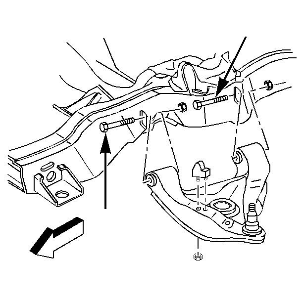
- In order to maintain adequate steering linkage clearance, install the bolts in the direction shown.
- Install the lower control arm front pivot bolt and the new nut.
- Install the lower control arm rear pivot bolt and the new nut.
- Tighten the lower control arm pivot bolts nuts with the front suspension loaded.
- Tighten the lower control arm front bolt to 115 N·m (85 lb ft).
- Tighten the lower control arm rear bolt to 98 N·m (72 lb ft).
- Remove the J 23028-A .
- Install the shock absorber. Refer to Shock Absorber Replacement .
- Install the stabilizer shaft link to the lower control arm. Refer to Stabilizer Shaft Link Replacement .
- Check the front wheel alignment. Refer to Wheel Alignment Specifications in Wheel Alignment.
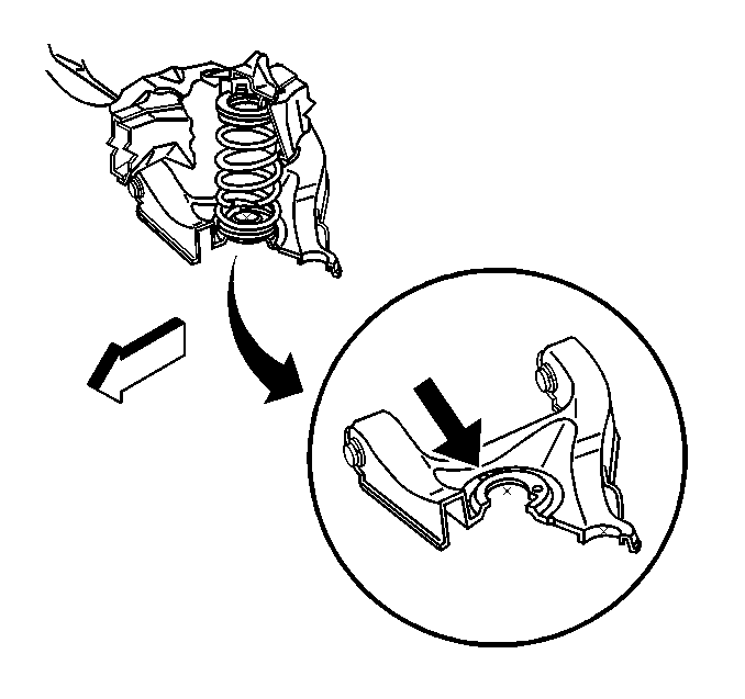
Ensure that front coil spring covers all or part of one inspection drain hole. The other hole must be partly or completely uncovered. Rotate coil spring as necessary.
Notice: Use the correct fastener in the correct location. Replacement fasteners must be the correct part number for that application. Fasteners requiring replacement or fasteners requiring the use of thread locking compound or sealant are identified in the service procedure. Do not use paints, lubricants, or corrosion inhibitors on fasteners or fastener joint surfaces unless specified. These coatings affect fastener torque and joint clamping force and may damage the fastener. Use the correct tightening sequence and specifications when installing fasteners in order to avoid damage to parts and systems.
Tighten
