For 1990-2009 cars only
Tools Required
J 8001 Dial Indicator Set, or equivalent
- Raise and suitably support the vehicle. Refer to Lifting and Jacking the Vehicle in General Information.
- Mark the location of the wheels to the wheel studs and mark the specific vehicle position on each tire and wheel (LF, LR, RF, RR).
- Remove the tire and wheel assemblies from the vehicle. Refer to Tire and Wheel Removal and Installation in Tires and Wheels.
- Remove the brake rotors from the vehicle, except for full floating type rear drive axles. Refer to Front Brake Rotor Replacement and Rear Brake Rotor Replacement in Disc Brakes.
- Remove any loose debris or corrosion from the hub/axle flange surface.
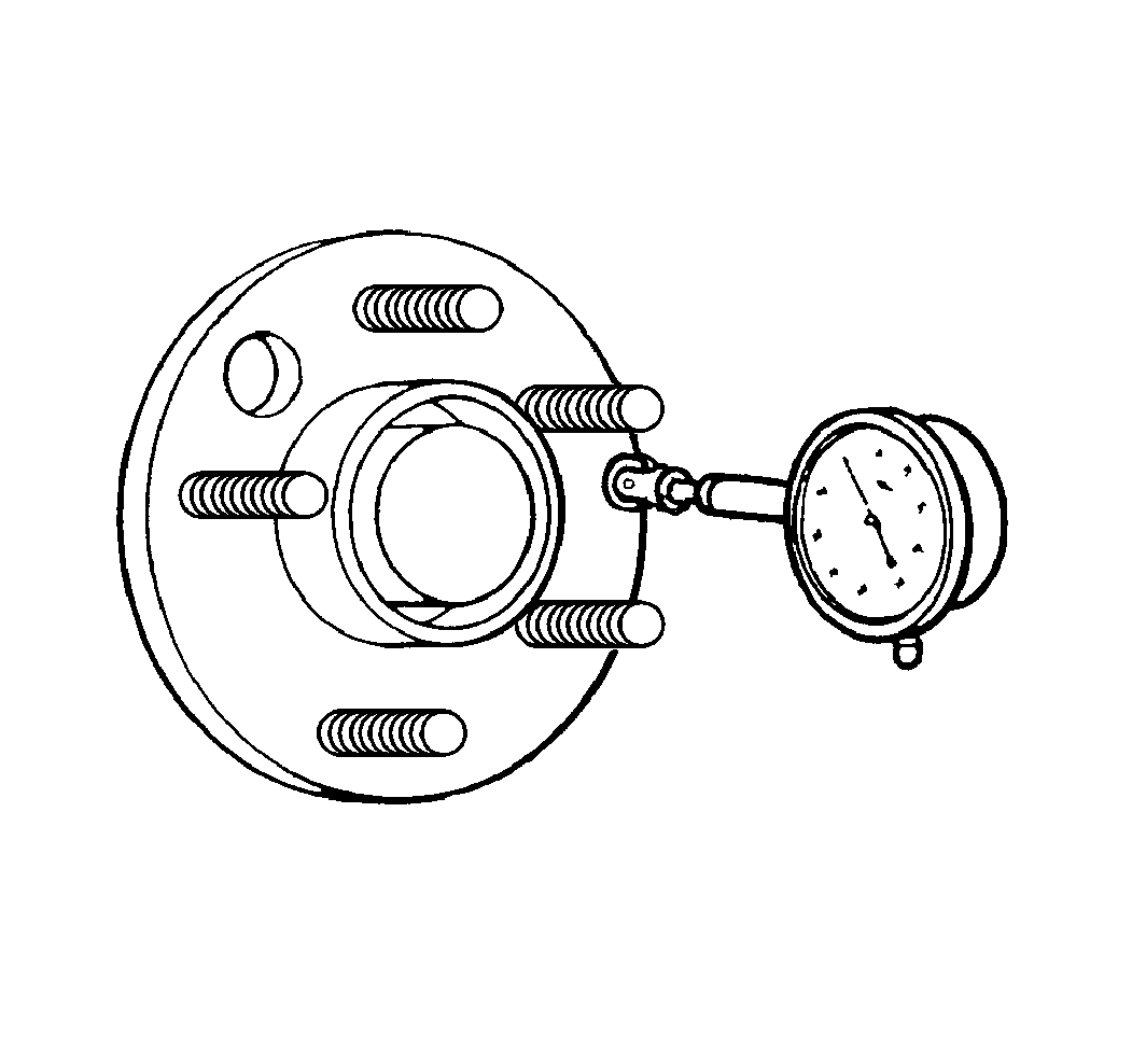
- Position the J 8001 , or equivalent, on the machined surface of the wheel hub/axle flange (or brake rotor on full-floating axles) outside of the wheel studs.
- Rotate the hub one complete revolution in order to find the low spot.
- Set the J 8001 , or equivalent, to zero at the low spot.
- Rotate the hub one more complete revolution and measure the total amount of wheel hub/axle flange runout.
- If the runout of the wheel hub/axle flange IS within specification, proceed to step 13.
- If the runout of the wheel hub/axle flange is marginal, the wheel hub may or may not be the source of the disturbance.
- If the runout of the wheel hub/axle flange is excessive, replace the wheel hub/axle flange. Measure the runout of the new wheel hub/axle flange. Refer to the appropriate procedure:
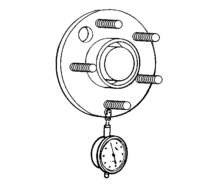
- Position the J 8001 , or equivalent, in order to contact the wheel mounting studs.
- Turn the hub one complete revolution to register on each of the wheel studs.
- Zero the J 8001 , or equivalent, on the lowest stud.
- Rotate the hub one more complete revolution and measure the total amount of wheel stud (stud circle) runout.
- If the runout of the wheel studs (stud circle) is marginal, the wheel studs may or may not be contributing to the disturbance.
- If the runout of the wheel studs (stud circle) is excessive, replace the wheel studs as necessary. Measure the runout of the new wheel studs. Refer to the appropriate procedure:

Specification (Guideline)
Wheel hub/axle flange runout tolerance guideline: 0.132 mm (0.005 in)
| • | Front Wheel Hub, Bearing, and Seal Replacement in Front Suspension |
| • | Rear Axle Shaft Replacement in Rear Drive Axle |

Measure the stud runout as close to the flange as possible.
Specification (Guideline)
Wheel stud runout tolerance guideline: 0.254 mm (0.010 in)
| • | Wheel Stud Replacement in Front Suspension |
| • | Wheel Stud Replacement in Rear Suspension |
