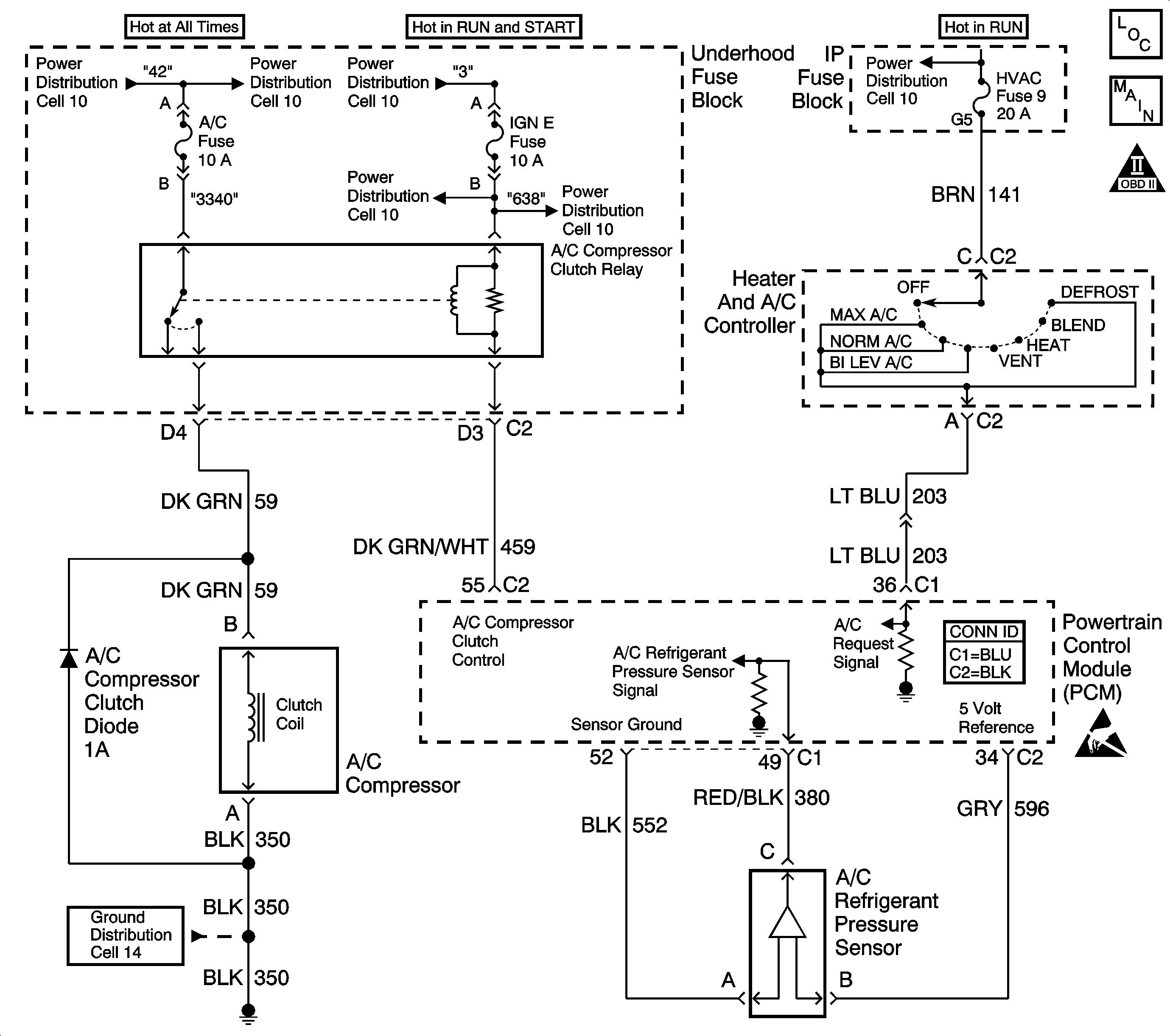
Circuit Description
The A/C refrigerant pressure sensor responds to changes in A/C refrigerant high side pressure. This input indicates how much load the A/C compressor is putting on the engine. The PCM uses this input in order to determine the Idle Air Control (IAC) position for idle speed. The PCM supplies the A/C refrigerant pressure sensor with a 5V reference and a ground circuit. A signal voltage is sent back to the PCM by the A/C refrigerant pressure sensor which is proportional to the A/C pressure. The operating range of the sensor is between 0 and 459 psi. At 0 psi the signal voltage will read between 0.20 V varying to 5.0 V at 459 psi or above.
Conditions for Running The DTC
The A/C refrigerant sensor pressure is more than 453 psi (4.90 volt) with the A/C requested.
OR
The A/C refrigerant sensor pressure is more than 363 psi (4.0 volt) with the A/C not requested
OR
The A/C refrigerant pressure sensor is less than 0 psi (0.10volt) when the intake air temperature is more than 0°C (32°F) and DTC P0112 or P0113 is not set.
OR
The A/C refrigerant sensor pressure is less than 0 psi (0.10 volt) when an IAT sensor DTC is present.
Conditions for Setting the DTC
Any of the above conditions are met for 15 seconds.
Action Taken When the DTC Sets
| • | The PCM records the operating conditions at the time the diagnostic fails. The Failure Records buffers stores this information. |
| • | The PCM stores a history DTC. |
| • | The PCM disables the A/C compressor clutch. |
Conditions for Clearing the DTC
| • | A History DTC clears after 40 consecutive warm up cycles without a fault. |
| • | Use a scan tool to clear the DTCs. |
Diagnostic Aids
| • | The DTC P0530 sets when the signal voltage falls outside of the normal possible range of the sensor. |
| • | If the actual pressure of the A/C system matches the scan tool readings, repair any A/C pressure problems before using this table. Refer to the Air Conditioning System section of the service manual. |
An intermittent may be caused by any of the following conditions:
| • | A poor connection |
| • | Rubbed through wire insulation |
| • | A broken wire inside the insulation |
Thoroughly check any circuitry that is suspected of causing the intermittent complaint. Refer to Intermittents and Poor Connections Diagnosis in Wiring Systems.
If a repair is necessary, refer to Wiring Repairs or Connector Repairs in Wiring Systems.
Test Description
The numbers below refer to the step numbers on the Diagnostic Table.
-
The Powertrain OBD System Check prompts the technician to complete some basic checks and store the freeze frame and failure records data on the scan tool if applicable. This creates an electronic copy of the data taken when the malfunction occurred. The information is then stored on the scan tool for later reference.
-
If the MAP or the TP sensor DTC is set, the malfunctioning circuit is diagnosed in these tables. Refer to the appropriate table.
-
An open or poor connection in a shared sensor ground circuit will cause other DTCs to be set. If no other DTCs were set, the malfunction must be between the sensor and the circuit splice.
-
Determines if the low voltage signal was from the sensor or the signal circuit. Jumping the signal circuit to the 5 volt reference checks the circuits, connections and the PCM.
-
An open in a shared 5 volt reference circuit can cause other DTCs to be set. If no other DTCs were set, the circuit must be open between the sensor and the circuit splice.
-
Replacement PCMs must be reprogrammed and the Crankshaft Position System Variation Learn Procedure must be performed. Refer to the latest Techline information for PCM reprogramming and also refer to the Crankshaft Position System Variation Learn for the Crankshaft Position System Variation Learn Procedure.
-
If no malfunctions have been found at this point and no additional DTCs were set, refer to Diagnostic Aids for additional checks and information.
Step | Action | Values) | Yes | No |
|---|---|---|---|---|
Was the Powertrain On-Board Diagnostic (OBD) System Check performed? | -- | Go to | ||
Were any MAP or TP DTCs also set? | -- | Go to MAP or TP DTC Tables | ||
3 | Does the A/C High side value read more than the specified value? | 4.0V (363 psi) | ||
4 | Disconnect the A/C pressure sensor electrical connector. Is the A/C high side value less than the specified value? | 1.0V (76 psi) | ||
5 | Is the A/C high side value less than the specified value? | 0.20V (0 psi) | ||
6 | Connect a DMM to B+ and probe the A/C refrigerant pressure sensor ground circuit. Does the DMM measure the specified voltage? | B+ | ||
7 |
Does the DVM measure near the specified voltage? | 5.0V | ||
8 |
Does the A/C compressor clutch remain engaged? | -- | ||
9 | Check for poor connections of the A/C refrigerant pressure sensor. If OK, replace the A/C refrigerant pressure sensor. Refer to Air Conditioning (A/C) Refrigerant Pressure Sensor Replacement in HVAC System-Manual. Is the action complete? | -- | -- | |
Check for an open or poor connection in the A/C refrigerant pressure sensor ground circuit. Refer to Wiring Repairs in Wiring Systems. Was a repair necessary? | -- | -- | ||
11 | Connect a DMM to ground and probe the A/C refrigerant pressure sensor signal circuit. Is the voltage more than the specified value? | 4.0V-6.0V | ||
Jumper the A/C refrigerant pressure sensor 5 volt reference and signal circuit terminals together. Does the scan tool A/C High side value read greater than the specified value? | 4.6V (421 psi) | |||
Check for an open or poor connection in the A/C refrigerant pressure sensor 5.0 volt reference circuit. Refer to Wiring Repairs in Wiring Systems. Was a repair necessary? | -- | -- | ||
14 |
Does the test lamp illuminate? | -- | ||
Check for poor connections on the PCM connector. If OK, replace the PCM. Refer to Powertrain Control Module Replacement . Is the action complete? | -- | -- | ||
16 | Check for a short to B+ in the A/C refrigerant pressure sensor signal circuit and repair as necessary. Refer to Wiring Repairs in Wiring Systems. Was a repair necessary? | -- | ||
17 |
Important: The Powertrain Control Module (PCM) uses a single 5.0 volt power supply to supply power to all the engine control components. If one component shorts its 5.0 volt reference circuit to ground or battery voltage, the other 5.0 volt reference circuits will also have a low or high voltage. Check the A/C refrigerant pressure sensor signal circuit for a short to the 5.0 volt reference circuit and repair as necessary. Refer to Wiring Repairs in Wiring Systems. Was a repair necessary? | -- | ||
18 | Connect a DMM to B+ and probe the A/C refrigerant pressure sensor signal circuit. Does the DMM read more than the specified value? | 0.5V | ||
19 | Check the A/C compressor clutch relay control circuit for a short to ground and repair as necessary. Refer to Wiring Repairs in Wiring Systems. Was a repair necessary? | -- | ||
20 | Did the A/C clutch disengage when the A/C relay was removed? | -- | ||
21 | Check for a short to ground or a short to the sensor ground in the A/C refrigerant pressure sensor signal circuit and repair as necessary. Refer to Wiring Repairs in Wiring Systems. Was a repair necessary? | -- | ||
22 | Check for an open in the A/C refrigerant pressure sensor signal circuit and repair as necessary. Refer to Wiring Repairs in Wiring Systems. Was a repair necessary? | -- | ||
23 | Replace the A/C compressor clutch relay. Refer to Compressor Relay Replacement in HVAC System. Is the action complete? | -- | -- | |
24 | Check for a short to B+ in the A/C compressor clutch ignition feed circuit, or for a malfunctioning A/C compressor clutch. Is the action complete? | -- | -- | |
25 |
Does the scan tool indicate that this diagnostic has ran and passed? | -- | ||
Check if any additional DTCs are set. Are any DTCs displayed that has not been diagnosed? | -- | Go to the applicable DTC table | System OK Go to Diagnostic Aids |
