MANUAL UPDATE-SEC. 6E1/6E2/6E3 CODE 33,34,63,64 (NON-TURBOS)

Model and Year: 1980-90 PASSENGER CARS AND TRUCKS
This bulletin revises the Manifold Absolute Pressure (MAP) Output Check Chart C-1D and updates Code 33, Code 34, Code 63, and Code 64 in the Service Manual section on "Driveability And Emissions" (Section 6E1, 6E2, and 6E3). This information applies to all MAP Sensors on 1980-1990 vehicles with gasoline engines (except turbocharged) with green (standard) MAP sensor electrical connector insert or the solid black MAP sensor electrical connector insert.
The revised chart and facing page information is as follows:
- Diagnostic Chart C-1D and facing page.
The updated chart and facing page information is as follows:
- Diagnostic Chart Code 33 and facing page. - Diagnostic Chart Code 34 and facing page. - Diagnostic Chart Code 63 and facing page. - Diagnostic Chart Code 64 and facing page.
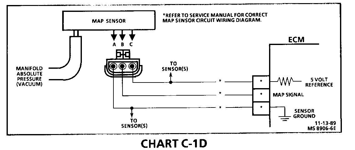
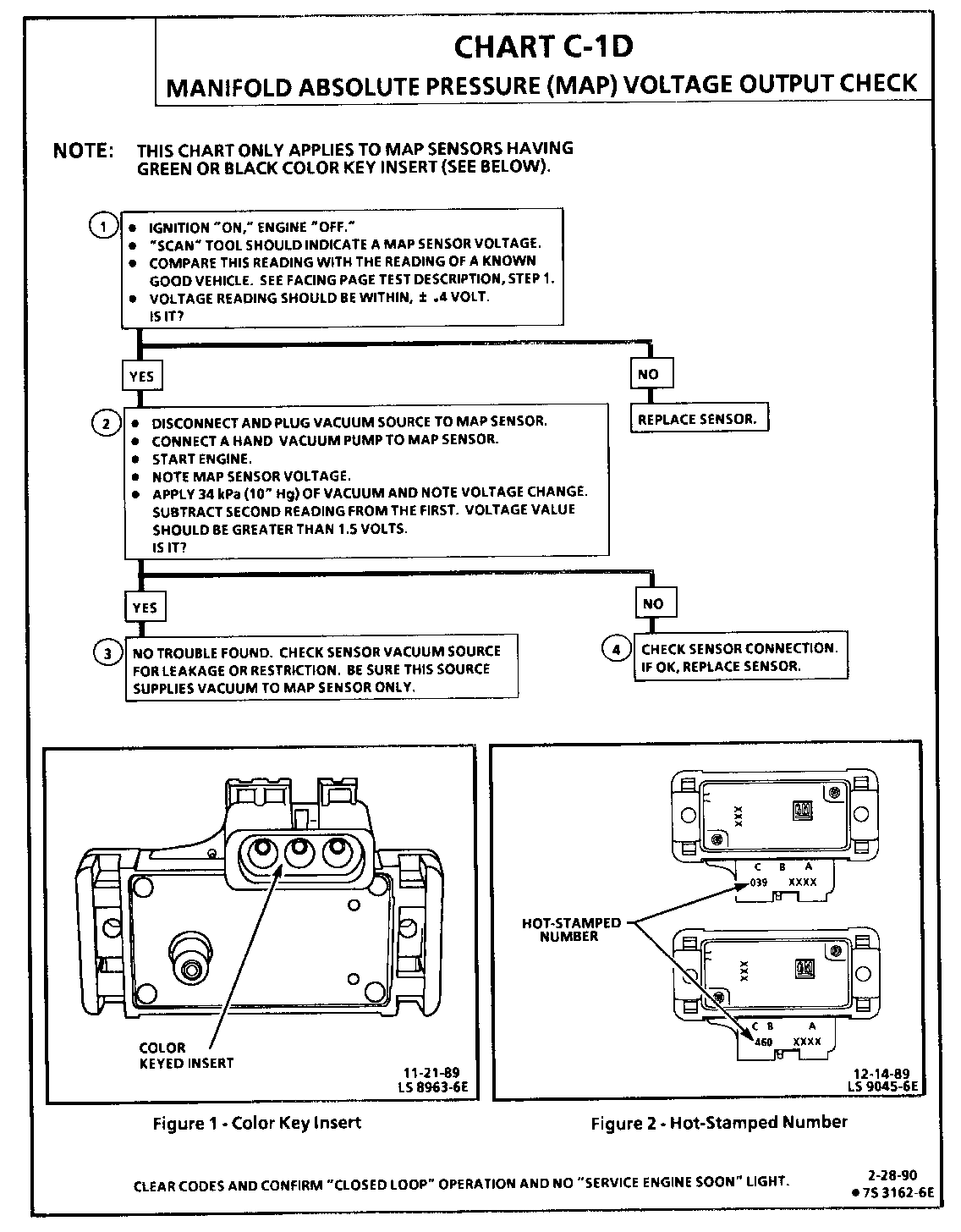
CHART C-1D MANIFOLD ABSOLUTE PRESSURE (MAP) VOLTAGE OUTPUT CHECK
Circuit Description:
The Manifold Absolute Pressure (MAP) sensor measures the changes in the intake manifold pressure which result from engine load (intake manifold vacuum) and rpm changes; and converts these into a voltage output. The ECM sends a 5 volt reference voltage to the MAP sensor. As the manifold pressure changed, the output voltage of the sensor also changes. By monitoring the sensor output voltage, the ECM knows the manifold pressure. A lower pressure (low voltage) output voltage will be about 1 - 2 volts at idle. While higher pressure (high voltage) output voltage will be about 4 - 4.8 at Wide Open Throttle (WOT). The MAP sensor is also used, under certain conditions, to measure barometric pressure, allowing the ECM to make adjustments for different altitudes. The ECM uses the MAP sensor to control fuel delivery and ignition timing.
Test Description: Numbers below refer to circled numbers on the diagnostic chart.
Important
Be sure to use the same Diagnostic Test Equipment for all measurements.
1. When comparing "Scan" readings to a known good vehicle, it is important to compare vehicles that use a MAP sensor having the same color insert or having the same "Hot Stamped" number. See figures on facing page.
2. Applying 34 kPa (10" Hg) vacuum to the MAP sensor should cause the voltage to change. Subtract second reading from the first. Voltage value should be greater than 1.5 volts. Upon applying vacuum to the sensor, the change in voltage should be instantaneous. A slow voltage change indicates a faulty sensor.
3. Check vacuum hose to sensor for leaking or restriction. Be sure that no other vacuum devices are connected to the MAP hose.
NOTE: Make sure electrical connector remains securely fastened.
4. Disconnect sensor from bracket and twist sensor by hand (only) to check for intermittent connection. Output changes greater than .1 volt indicate a bad connector or connection. If OK, replace sensor.
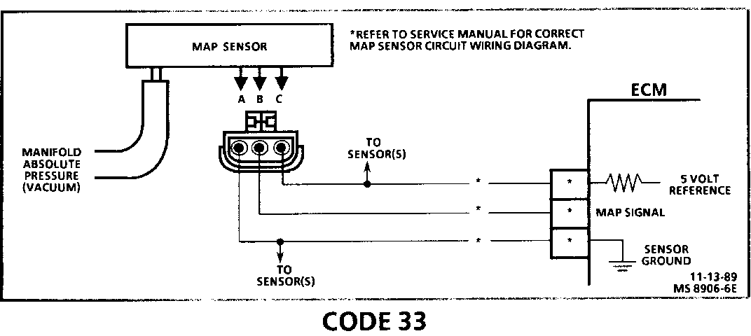
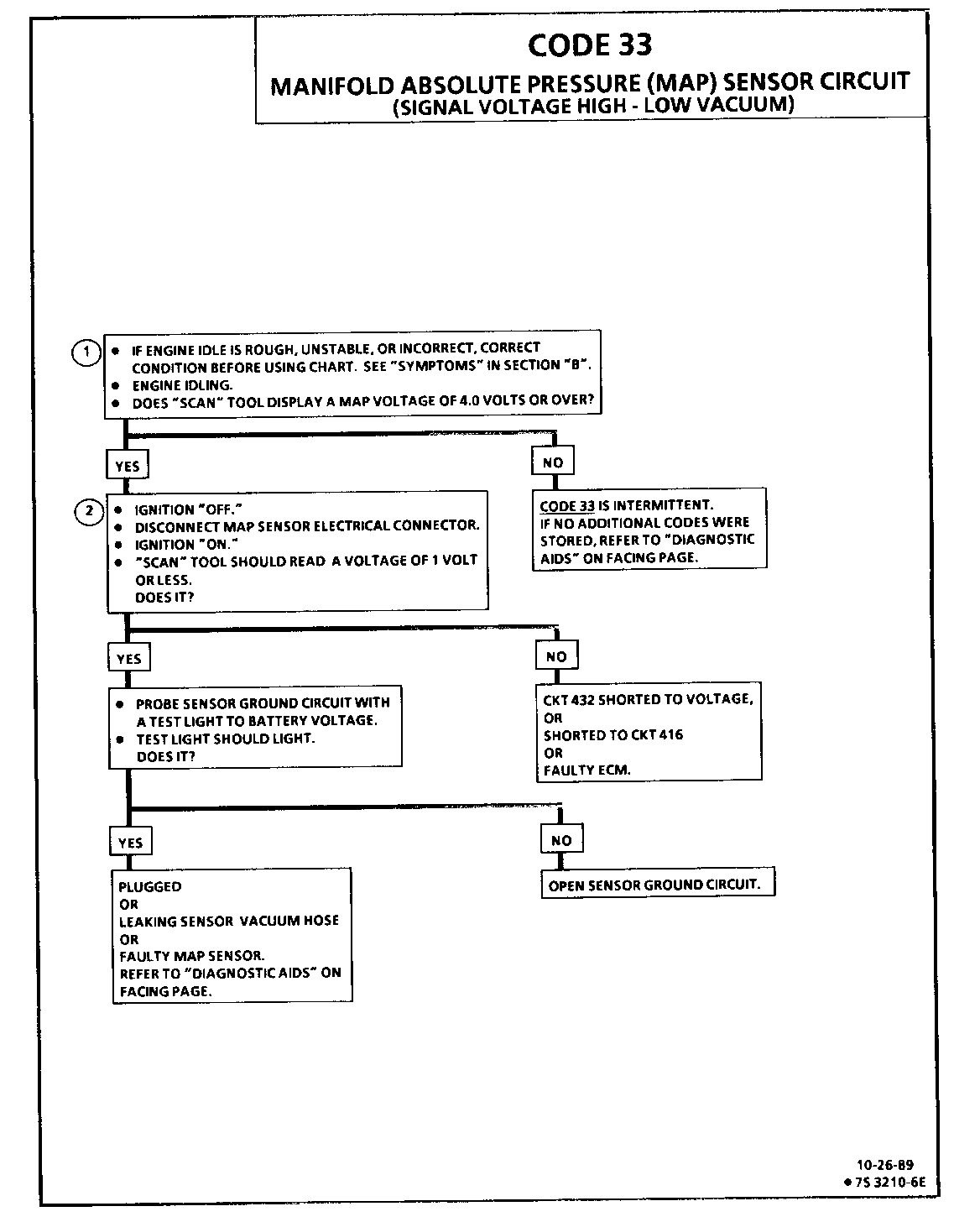
CODE 33 MANIFOLD ABSOLUTE PRESSURE (MAP) OUTPUT CHECK (SIGNAL VOLTAGE HIGH - LOW VACUUM)
Circuit Description:
The Manifold Absolute Pressure (MAP) sensor responds to changes in manifold pressure (vacuum). The ECM receives this information as a signal voltage that will vary from about 1 to 1.5 volts at closed throttle (idle) to 4.5 - 4.8 volts at wide open throttle (low vacuum).
If the MAP sensor fails, the ECM will substitute a fixed MAP value and use the Throttle Position Sensor (TPS) to control fuel delivery.
Test Description: Numbers below refer to circled numbers on the diagnostic chart.
1. This step will determine if Code 33 is the result of a hard failure or an intermittent condition.
A Code 33 will set under the following conditions:
MAP signal voltage is too high (low vacuum). TPS less than 2%. These conditions exist longer than 5 seconds.
2. This step simulates conditions for a Code 34. If the ECM recognizes the change, the ECM and CKT 416 and CKT 432 are OK. If CKT 469 is open, there may also be a stored Code 23.
Diagnostic Aids:
With the ignition "ON" and the engine stopped, the manifold pressure is equal to atmospheric pressure and the signal voltage will be high. This information is used by the ECM as an indication of vehicle altitude. Comparison of this reading with a known good vehicle with the same sensor is a good way to check accuracy of a "suspect" sensor. Readings should be the same .4 volt.
A Code 33 will result if CKT 469 is open or if CKT 432 is shorted to voltage or to CKT 416.
If Code 33 is intermittent, refer to Section "B".
NOTE: Make sure electrical connector remains securely fastened.
Check all connections.
Disconnect sensor from bracket and twist sensor by hand (only) to check for intermittent connections. Output changes greater than .1 volt indicates a bad connector or connection. If OK, replace sensor.
Refer to CHART C-1D, MAP sensor voltage output check for further diagnosis.
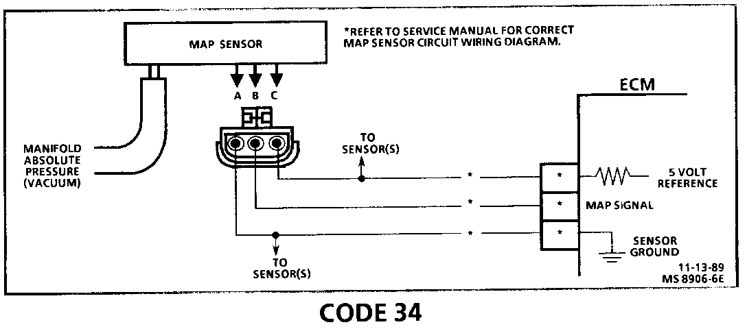
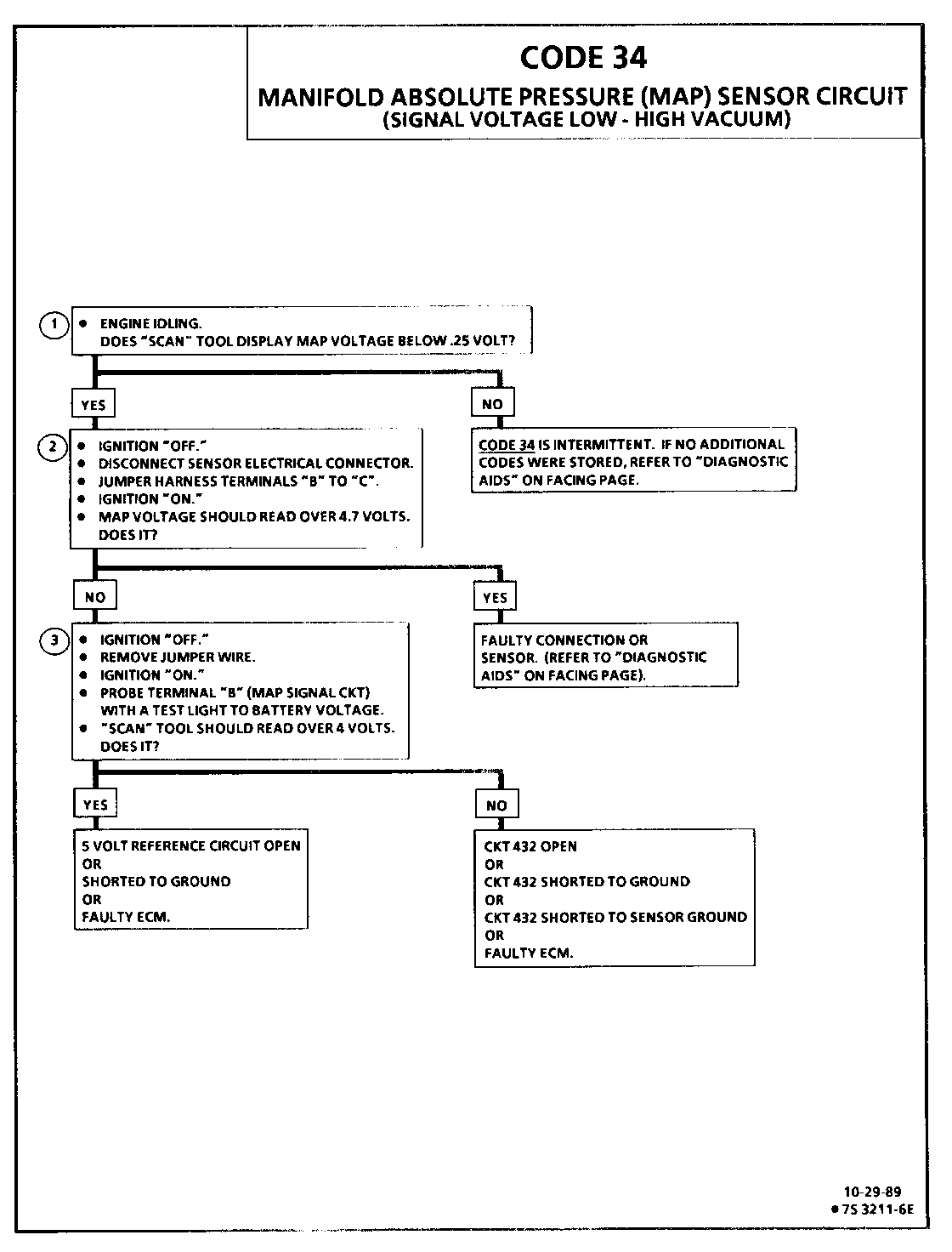
CODE 34 MANIFOLD ABSOLUTE PRESSURE (MAP) SENSOR CIRCUIT (SIGNAL VOLTAGE LOW - HIGH VACUUM)
Circuit Description:
The Manifold Absolute Pressure (MAP) sensor responds to changes in manifold pressure (vacuum). The ECM receives this information as a signal voltage that will vary from about 1 to 1.5 volts at closed throttle (idle) to 4.5 - 4.8 volts at wide open throttle (low vacuum).
If the MAP sensor fails, the ECM will substitute a fixed MAP value and use the Throttle Position Sensor (TPS) to control fuel delivery.
Test Description: Numbers below refer to circled numbers on the diagnostic chart.
1. This step determines if Code 34 is the result of a hard failure or an intermittent condition. A Code 34 will set when MAP signal voltage is too low and the ignition is "ON."
2. Jumpering harness terminals "B" to "C" (5 volts to signal circuit) will determine if the sensor is at fault, or if there is a problem with the ECM or wiring.
3. The "Scan" tool may not display 5 volts. The important thing is that the ECM recognizes the voltage as more than 4 volts, indicating that the ECM and CKT 432 are OK.
Diagnostic Aids:
An intermittent open in CKT 432 or CKT 416 will result in a Code 34. With the ignition "ON" and the engine "OFF," the manifold pressure is equal to atmospheric pressure and the signal voltage will be high. This information is used by the ECM as an indication of vehicle altitude.
Comparison of this reading with a known good vehicle with the same sensor is a good way to check accuracy of a "suspect" sensor. Readings should be the same +/- .4 volts. Also CHART C-1D can be used to test the MAP sensor. Refer to "Intermittents" in Section
NOTE: Make sure electrical connector remains securely fastened.
Check all connections.
Disconnect sensor from bracket and twist sensor by hand (only) to check for intermittent connections. Output changes greater than .1 volt indicates a bad connector or connection. If OK, replace sensor.
Refer to CHART C-1D, MAP sensor voltage output check for further diagnosis.
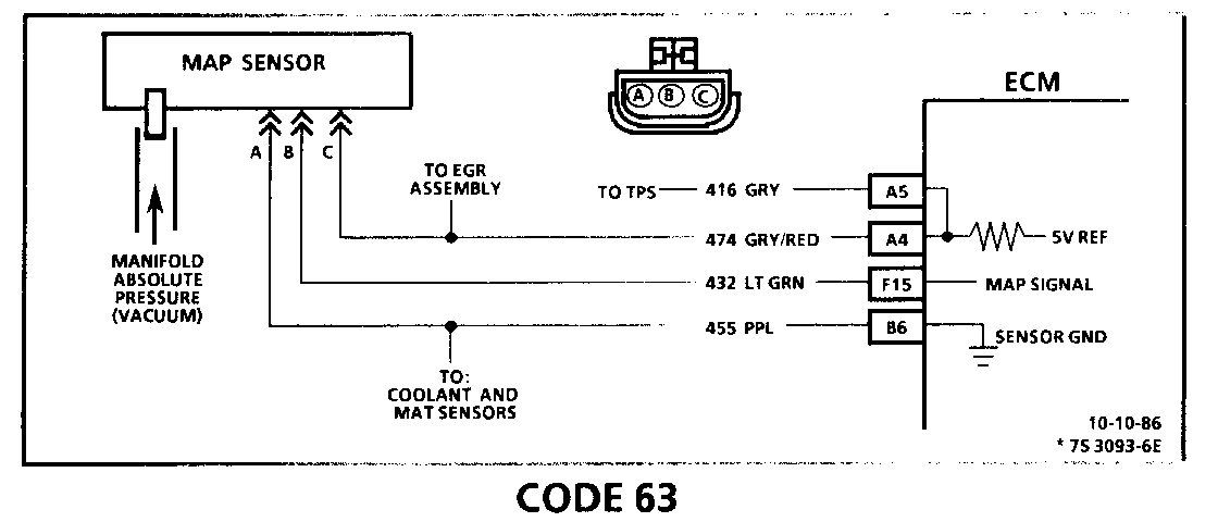
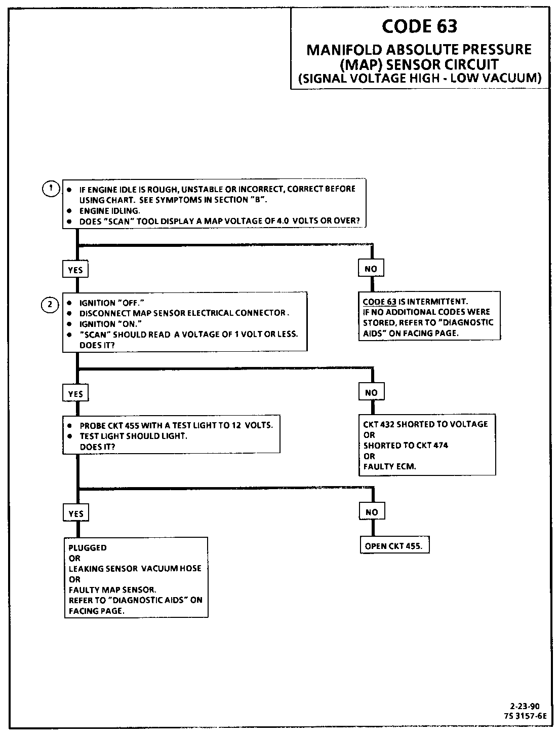
CODE 63 MANIFOLD ABSOLUTE PRESSURE (MAP) SENSOR CIRCUIT (SIGNAL VOLTAGE HIGH - LOW VACUUM)
Circuit Description:
The Manifold Absolute Pressure (MAP) sensor responds to changes in manifold pressure (vacuum). The ECM receives this information as a signal voltage that will vary from about 1 to 1.5 volts at closed throttle (idle) to 4.5 - 4.8 volts at wide open throttle (low vacuum).
If the MAP sensor fails, the ECM will substitute a fixed MAP value and use the Throttle Position Sensor (TPS) to control fuel delivery.
Test Description: Numbers below refer to circled numbers on the diagnostic chart.
1. Code 63 will set when:
Engine running. Manifold pressure greater than 75.3 kPa (A/C "OFF") 81.2 kPa (A/C "ON"). Throttle angle less than 2%. Conditions met for 2 seconds. Engine misfire or a low unstable idle may set Code 63.
2. With the MAP sensor disconnected, the ECM should see a low voltage if the ECM and wiring are OK.
Diagnostic Aids:
With the ignition "ON" and the engine stopped, the manifold pressure is equal to atmospheric pressure and the signal voltage will be high. This information is used by the ECM as an indication of vehicle altitude. Comparison of this reading with a known good vehicle with the same sensor is a good way to check accuracy of a "suspect" sensor. Readings should be the same .4 volt.
If idle is rough or unstable, refer to symptoms in Section "B" for items which can cause an unstable idle.
An open in CKT 455 or the connection will result in a Code 63.
NOTE: Make sure electrical connector remains securely fastened.
Check all connections.
Disconnect sensor from bracket and twist sensor by hand (only) to check for intermittent connections. Output changes greater than .1 volt indicates a bad connector or connection. If OK, replace sensor.
Refer to CHART C-1D, MAP sensor voltage output check for further diagnosis.
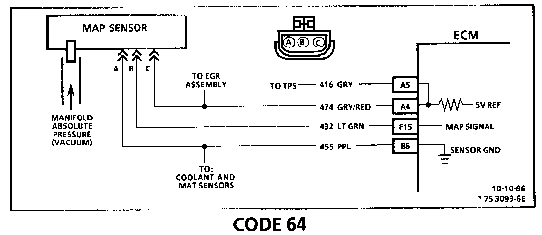
CODE 64 MANIFOLD ABSOLUTE PRESSURE (MAP) SENSOR CIRCUIT (SIGNAL VOLTAGE LOW - HIGH VACUUM)
Circuit Description:
The Manifold Absolute Pressure (MAP) sensor responds to changes in manifold pressure (vacuum). The ECM receives this information as a signal voltage that will vary from about 1 to 1.5 volts at closed throttle (idle) to 4.5 - 4.8 volts at wide open throttle (low vacuum).
If the MAP sensor fails, the ECM will substitute a fixed MAP value and use the Throttle Position Sensor (TPS) to control fuel delivery.
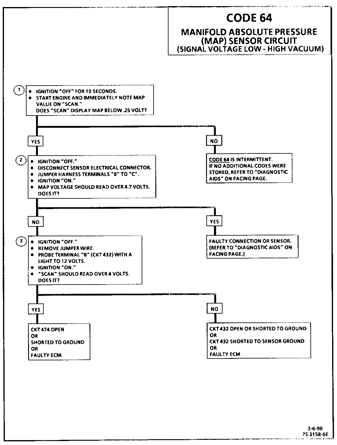
Test Description: Numbers below refer to circled numbers on the diagnostic chart.
1. Code 64 will set if:
Engine rpm less than 600.
Manifold pressure reading less than 13 kPa.
Conditions met for 1 second.
or
Engine rpm greater than 600.
Throttle angle over 20%.
Manifold pressure less than 13 kPa.
Conditions met for 1 second.
2. This test to see if the sensor is at fault for the low voltage, or if there is an ECM or wiring problem.
3. This simulates a high signal voltage to check for an open in CKT 432. If the test light is bright during this test, CKT 432 is probably shorted to ground. If "Scan" reads over 4 volts at this test, CKT 474 can be checked by measuring the voltage at terminal "C" (should be 5 volts).
Diagnostic Aids:
An intermittent open in CKTs 432 or 474 will result in a Code 64.
With the ignition "ON" and the engine "OFF," the manifold pressure is equal to atmospheric pressure and the signal voltage will be high. This information is used by the ECM as an indication of vehicle altitude.
Comparison of this reading with a known good vehicle with the same sensor is a good way to check accuracy of a "suspect" sensor. Readings should be the same +/- .4 volts. Also CHART C-1D can be used to test the MAP sensor. Refer to "Intermittents" in Section
NOTE: Make sure electrical connector remains securely fastened.
Check all connections.
Disconnect sensor from bracket and twist sensor By hand (only) to check for intermittent connections. Output changes greater than .1 volt indicates a bad connector or connection. If OK, replace sensor.
Refer to CHART C-1D, MAP sensor voltage output check for further diagnosis.
General Motors bulletins are intended for use by professional technicians, not a "do-it-yourselfer". They are written to inform those technicians of conditions that may occur on some vehicles, or to provide information that could assist in the proper service of a vehicle. Properly trained technicians have the equipment, tools, safety instructions and know-how to do a job properly and safely. If a condition is described, do not assume that the bulletin applies to your vehicle, or that your vehicle will have that condition. See a General Motors dealer servicing your brand of General Motors vehicle for information on whether your vehicle may benefit from the information.
