GM Service Manual Online
For 1990-2009 cars only

Object Number: 620952  Size: SF
(1)EVAP Canister Purge Solenoid Valve
(2)Air Inlet Line
(3)EVAP Canister Vent Solenoid Valve
(4)Purge Line to Engine
(5)Air Cleaner
(6)Throttle Body
(7)EVAP Service Port (if equipped)
(8)Purge Line from Canister
(9)EVAP Canister
(10)ORVR Vent Line (To FLVV)
(11)Fuel Tank
(12)EVAP (vapor) Line
(13)Vapor Pressure Line
(14)Fuel Tank Pressure Sensor
(15)EVAP Pressure Switching Solenoid
(16)EVAP Vapor Pressure Line (Canister and Purge Side)
(17)EVAP Vapor Pressure Line (Fuel Tank Side)
(18)Drain Line

The evaporative emission (EVAP) control system limits fuel vapor emissions to the atmosphere. The EVAP system transfers the fuel vapor from a sealed fuel tank to an EVAP canister containing activated carbon. The EVAP canister stores the fuel vapors until the engine is able to use the vapors.

The EVAP canister is located at the rear of the vehicle next to the fuel tank. The EVAP canister is larger than in previous years. The larger canister and the relocation to near the fuel tank was necessary for integration with the vehicle's onboard refueling vapor recovery (ORVR) system.
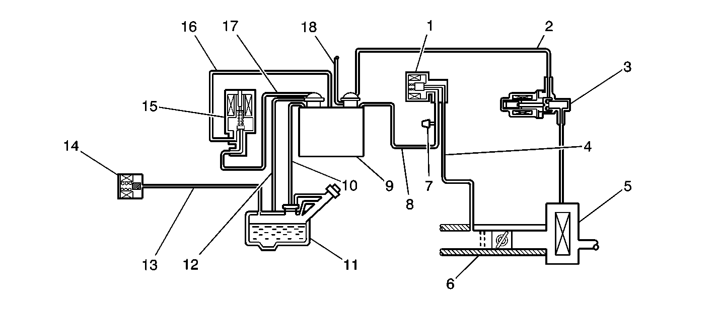
EVAP Control System Operation


Object Number: 621105  Size: LF
(1)Fuel Tank Pressure Sensor
(2)Fuel Tank Pressure Sensor (1st Design) Drain Port
(3)Fuel Tank Pressure Sensor Supply Hose
(4)EVAP Pressure Switching Solenoid
(5)Drain Line
(6)Air Inlet Line (To Air Cleaner)
(7)EVAP Vapor Line (To Fuel Tank )
(8)Purge Line (To EVAP Canister Purge Solenoid Valve)
(9)ORVR Vent Line (To FLVV on Fuel Tank)
(10)EVAP Canister Vent Solenoid Valve
(11)EVAP Canister Purge Solenoid Valve
(12)Air Cleaner
(13)Throttle Body
(14)EVAP Service Port
(15)EVAP Canister
(16)Fuel Tank
(17)Fuel Tank Pressure Sensor
(18)EVAP Pressure Switching Solenoid
(19)EVAP Canister Control Valve Drain
(20)EVAP Canister Assembly
(21)Fuel Tank Pressure Sensor (2nd Design) Drain Port

The EVAP system transfers the fuel vapor from the fuel tank to the EVAP canister. Once the engine is fully warmed up and operating above a specified speed, the stored fuel vapors are dispersed into the intake manifold. The fuel vapors are purged from the carbon element in the EVAP canister by the intake air flow and consumed in the normal combustion process.

The EVAP control system is required to detect evaporative fuel system leaks between the fuel filler cap and the purge valve. The system integrity can be tested by applying a vacuum signal, ported or manifold, to the fuel tank. Sealing the other end of the EVAP system enables the applied vacuum to create a small pressure that can be monitored for leaks. The powertrain control module (PCM) monitors the positive or negative pressure in the fuel tank. The PCM is able to detect any abnormal conditions by the fluctuation of this pressure. The PCM warns the driver of a malfunction in the EVAP system by illuminating the malfunction indicator lamp (MIL).

EVAP Canister Vent Valve


Object Number: 621142  Size: SH

The EVAP canister vent valve is control by the PCM. The EVAP canister vent valve controls the flow of fresh air that passes through the EVAP canister. The fuel vapors stored in the canister are mixed with the fresh air supply and purged when the vent and purge valves are both open. The PCM closes the EVAP canister vent valve in order to seal the EVAP system for leak diagnosis.

EVAP Canister Purge Valve

The EVAP canister purge valve controls the flow of fuel vapors into the intake manifold. The EVAP canister purge valve is normally open when the engine is warm and operating above an idle. The EVAP canister purge valve is control by the PCM.

EVAP Pressure Switching Solenoid

The EVAP pressure switching solenoid is controlled by the PCM. When the EVAP pressure switching solenoid turns ON, the vapor pressure on the purge side of the EVAP system is allowed to enter the fuel tank.

Fuel Tank Pressure Sensor


Object Number: 350039  Size: SH

The fuel tank pressure (FTP) sensor (4) contains a silicon chip that changes electrical resistance when pressure is applied. The fuel tank pressure sensor converts the positive or negative pressure that is applied to the sensor's pressure port (2) into an electrical signal. The fuel tank pressure sensor amplifies the electrical signal and sends the signal to the PCM. There are 2 fuel tank pressure sensor designs in production. Both designs incorporate a drain port that is connected to the EVAP canister drain line. The first design (1) has the drain port located on top of the sensor. The second design (3) has the drain port located behind the pressure port (2). Be sure to connect the correct hose to the correct port when servicing or replacing the fuel tank pressure sensor.

Results Of Incorrect Operation

A poor idle, stalling, and poor driveability can be caused by:

    • A damaged EVAP canister
    • Any EVAP hoses that are split, cracked, or incorrectly connected to the proper tubes
    • A malfunctioning purge valve

Evidence of fuel loss or fuel vapor odor can be caused by:

    • Any fuel leaking from the fuel pipes
    • A cracked or damaged EVAP canister
    • Any disconnected, misrouted, kinked, deteriorated, or damaged vapor hoses
    • Any broken or leaking solenoids or components