The powertrain control module (PCM) is a precision unit consisting of
a one chip microprocessor, an A/D (analog-to-digital) converter, and
an I/O (input/output) unit. The PCM is an essential part of the
electronic control system. The PCM is responsible for such major
functions as control of the fuel injectors, the idle air control
(IAC) valve, the fuel pump relay, etc. The PCM performs the OBD II
diagnostic tests of the emission related systems. The PCM supplies
a buffered voltage, called reference voltage, to the various information
sensors and switches. The PCM controls most components with an
electronic switch that completes a ground circuit when turned ON.
The electronic switch is commonly referred to as an output driver.
The PCM is also responsible for a self-diagnosis function and a
fail-safe function.
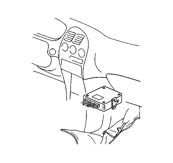
The PCM is located in the center console below the entertainment center
(radio/cassette/CD player).
Self-Diagnosis Function
The powertrain control module (PCM) diagnoses any troubles which may
occur in the engine control system when the ignition switch is in the ON position
with the engine running. The PCM indicates a malfunction by illuminating
the malfunction indicator lamp (MIL) when a fault occurs in any
of the following systems:
| • | The heated oxygen sensor 1 (HO2S 1) |
| • | The heated oxygen sensor 2 (HO2S 2) |
| • | The engine coolant temperature (ECT) sensor |
| • | The throttle position (TP) sensor (including the CTP switch) |
| • | The vehicle speed sensor (VSS) |
| • | The intake air temperature (IAT) sensor |
| • | The mass air flow (MAF) sensor |
| • | The camshaft position (CMP) sensor |
| • | The crankshaft position (CKP) sensor |
| • | The knock sensor (KS) system |
| • | The evaporative emission (EVAP) control system |
| • | The idle air control (IAC) system |
| • | The CMP actuator solenoid system |
| • | The central processing unit (CPU) of the PCM |
When the PCM detects a malfunction in one of the above areas, the PCM
will illuminate or flash the MIL in order to notify the driver of the occurrence
of a fault. The PCM will store a DTC when the PCM illuminates
the MIL.
The PCM will turn OFF the MIL after 3 consecutive ignition cycles without
the malfunction occurring. The DTC will remain stored in the PCM memory after
the MIL is OFF.
Fail-Safe Function
When a malfunction occurs within the engine control system, the PCM
maintains control over the fuel injection system, the idle speed
control system, etc. The PCM controls these systems by using calculated
values and/or backup programs stored within the PCM.
This function is called the fail-safe function. With the fail-safe function,
a certain level of engine performance is available even when a malfunction
occurs. The fail-safe function prevents a complete loss of engine
performance.
The systems covered by the fail-safe function are as follows:
| • | The HO2S heater circuits |
| • | The fuel cut-off for ignition system failures |
Control Module Learning Ability
The powertrain control module has a "learning" ability which
enables the control module to make corrections for minor variations in the
fuel system. This learning ability can improve driveability. Disconnecting
the battery resets the learning process. A change in the vehicle's
performance may be noticed when a reset occurs. The vehicle operator
can teach the control module in order to regain some of the lost
vehicle performance.
In order to teach the control module, ensure that the engine is at operating
temperature and drive the vehicle at part throttle with moderate acceleration.
The vehicle may also be operated at idle conditions until normal
performance returns.
Check Mode
The PCM has the ability to operate in the Normal mode or in the Check
Mode. The 2 modes of operation are identical except that when the
PCM is operating in the Check Mode, the PCM has an increased ability
to detect malfunctions. In order to request that the PCM operate
in the Check Mode, scan tool communication with the PCM is necessary.
For information on the use of the Check Mode in diagnosing driveability
concerns, refer to
Service Bay Test
.
PCM Output Controls
The powertrain control module (PCM) can be directed by a scan tool to
operate certain solenoids, valves, motors, and switches. This scan tool function
is generally referred to as Output Controls. The Output Controls
can be found under Special Functions selection of the scan tool.
Some Output Controls may be disabled by the PCM during certain
types of vehicle operation. Operating a PCM controlled device
with the scan tool should be limited to a maximum of ten seconds
per test period.
Data Link Connector (DLC)
Important: Do not use a scan tool that displays faulty data. Report the scan tool
problem to the manufacturer. Use of a faulty scan tool can result in misdiagnosis
and unnecessary parts replacement.
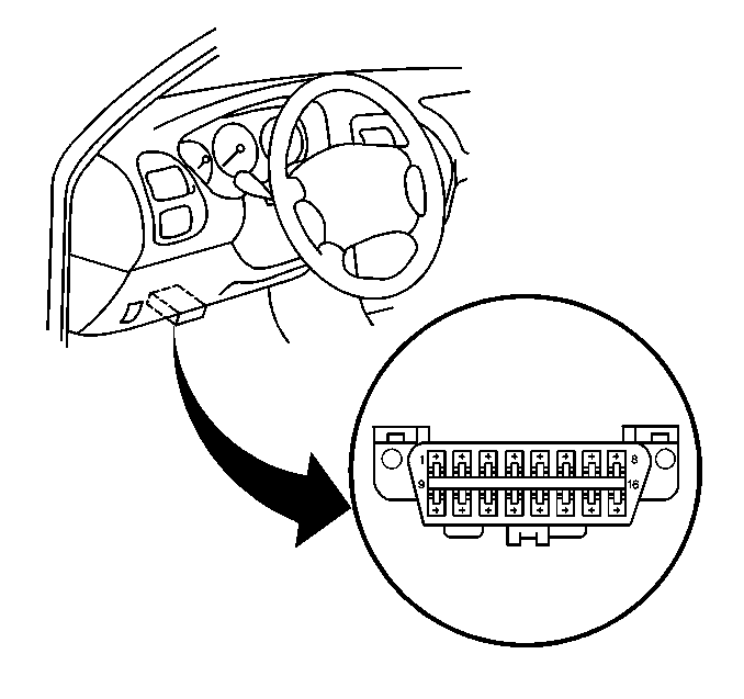
The provision for communicating with the control module is the data
link connector (DLC). The DLC is located under the instrument panel
to the left of the steering column. The DLC is used to connect to
a scan tool. Some common uses of the scan tool are listed below:
| • | Identifying stored diagnostic trouble codes (DTCs) |
| • | Performing output control tests |
| • | Reading the serial data |
Reading Diagnostic Trouble Codes
The procedure for reading diagnostic trouble codes is to use a diagnostic
scan tool. Follow the instructions supplied by the scan tool manufacturer
in order to read DTCs accurately.
Clearing Diagnostic Trouble Codes
Important: Do not clear the DTCs unless directed to do so by the service information
provided for each diagnostic procedure. The Freeze Frame data which may help
diagnose an intermittent fault will be erased from the memory
when the DTCs are cleared.
The PCM will begin to count the warm-up cycles when the fault that caused
the DTC to be stored into memory has been corrected. The DTC will automatically
be cleared from the PCM memory when the PCM has counted 40
consecutive warm-up cycles with no further faults detected.
Diagnostic trouble codes (DTCs) can be cleared using a scan tool. In
order to clear DTCs, use the scan tools Clear DTC Information function.
Follow the instructions supplied by the scan tool manufacturer.
Aftermarket (Add-On) Electrical and Vacuum Equipment
Notice: Connect any add-on electrically operated equipment to the vehicle's
electrical system at the battery (power and ground) in order to prevent damage
to the vehicle.
Notice: Do not attach add-on vacuum operated equipment to this vehicle. The
use of add-on vacuum equipment may result in damage to vehicle components
or systems.
Aftermarket (add-on) electrical and vacuum equipment is
defined as any equipment installed on a vehicle after leaving the factory
that connects to the vehicles electrical or vacuum systems. No
allowances have been made in the vehicle design for addition of
this type of equipment.
Add-on electrical equipment may cause the engine control system to malfunction
even when the add-on electrical equipment is installed properly. Portable
telephones and radios may also cause engine control system malfunctions
even when not connected to the vehicles electrical system. The
first step in diagnosing any engine control system problem is
to remove all aftermarket electrical equipment from the vehicle.
Diagnosis may proceed in the normal manner after eliminating aftermarket
equipment as a cause of the engine control system malfunction.
Electrostatic Discharge (ESD) Damage
Notice: In order to prevent possible Electrostatic Discharge damage to the PCM,
Do Not touch the connector pins or the soldered components on the circuit
board.
Electronic components used in the engine control system
are often designed to operate at very low voltages. Electronic components
are susceptible to damage caused by electrostatic discharge. Less
than 100 volts of static electricity can cause damage to
some of the electronic components. There are several ways for
a person to become statically charged. The most common methods
of charging are by friction and by induction. An example of charging
by friction is a person sliding across a car seat. Charging by induction
occurs when a person with well insulated shoes stands near a highly
charged object and momentarily touches ground. Charges of the same
polarity are drained off leaving the person highly charged with
the opposite polarity. Therefore, use care when handling and testing
electronic components in order to avoid electrostatic charges
that can cause electronic component damage.
Input Components
The PCM supplies a buffered (reference) voltage to the various information
sensors and switches. The PCM monitors the input components for
circuit continuity and out-of-range values. The PCM also provides
performance checking. Performance checking refers to the PCM
indicating a fault when the signal from an input does not seem
reasonable, i.e., a throttle position (TP) sensor that indicates
a high throttle position at low engine loads or low manifold absolute
pressure sensor voltage. The input components may include, but
are not limited to the following sensors and switches:
| • | The vehicle speed sensor (VSS) |
| • | The crankshaft position (CKP) sensor |
| • | The throttle position (TP) sensor |
| • | The engine coolant temperature (ECT) sensor |
| • | The camshaft position (CMP) sensor |
| • | The mass air flow (MAF) sensor |
| • | The heated oxygen sensor (HO2S) |
| • | The fuel tank pressure (FTP) sensor |
| • | The power steering pressure (PSP) switch, if equipped |
| • | The transmission range switch (A/T only) |
| • | The A/C compressor control module (A/C relay) |
Output Components
The PCM is responsible for the control and operation of many output
components. The PCM controls many components with an electronic
switch called an output driver that completes a ground circuit when
turned ON. The PCM monitors the output components for the proper
response to the PCM commands. Components where functional monitoring
is not feasible will be monitored for circuit continuity and
out-of-range values if applicable.
Output components to be monitored include, but are not limited to the
following circuits:
| • | The idle air control (IAC) valve |
| • | The CMP actuator solenoid valve |
| • | The circuit opening relay |
| • | The malfunction indicator lamp (MIL) control |
| • | The A/C compressor control module (A/C relay) |
| • | The electronic transaxle controls |
Catalyst Monitor Diagnostic Operation
The powertrain control module (PCM) uses certain diagnostic strategies
known as primary system based diagnostics that evaluate the various
primary system operations. The primary system based diagnostics also
evaluate the various primary system operations affect on vehicle
emissions. Some of the primary system based diagnostics are listed
here with a brief functional description of the diagnostics involved.
The OBD 2 catalyst monitor diagnostic measures the oxygen storage capacity
of the 3-way catalytic converter (TWC). Heated oxygen sensors (HO2S) are installed
before (pre-catalyst) and after (post-catalyst) the TWC. Voltage
variations between the sensors allow the PCM to determine the
performance of the TWC catalyst. When the TWC catalyst becomes less
effective in promoting chemical reactions, the catalyst's capacity
to store and release oxygen is generally degraded. The OBD 2 catalyst
monitor diagnostic is based on a correlation between the conversion
efficiency of the TWC catalyst and the oxygen storage capacity of
the catalyst. A good catalyst, e.g., 95 percent hydrocarbon
conversion efficiency, will show a relatively flat output voltage
on the post-catalyst sensor, HO2S 2. A degraded catalyst, 65 percent
hydrocarbon conversion, will show greatly increased activity in the
output voltage from the post catalyst HO2S.
The post-catalyst HO2S is used to measure the oxygen storage and release
capacity of the catalyst in the TWC. A high oxygen storage capacity indicates
a good catalyst. A low oxygen storage capacity indicates a failing
catalyst. The TWC and the HO2S 2 must be at operating temperature
in order to achieve the correct oxygen sensor voltages, like those
shown in the post-catalyst HO2S Outputs graphic.
The catalyst monitor diagnostic is sensitive to the following conditions:
Exhaust system leaks may cause any of the following results:
| • | A false failure for a normally functioning, good catalyst. |
| • | Prevent a degraded catalyst from failing the catalyst monitor
diagnostic. |
| • | Prevent the catalyst monitor diagnostic from running. |
The presence of HO2S contaminants may prevent the catalyst monitor diagnostic
from functioning properly.
Three-Way Catalyst Oxygen Storage Capacity
The TWC catalyst must be monitored for efficiency. In order to accomplish
this, the control module monitors the pre-catalyst (HO2S 1)
and post-catalyst (HO2S 2) oxygen sensors. When the TWC is operating
properly, the post-catalyst oxygen sensor will have significantly
less activity than the pre-catalyst oxygen sensor. The TWC stores
and releases oxygen as needed during the normal reduction and oxidation
process. The control module will calculate the oxygen storage capacity
using the difference between the pre-catalyst and post-catalyst oxygen
sensor voltage levels. If the activity of the post-catalyst oxygen
sensor approaches that of the pre-catalyst oxygen sensor, the catalyst's
efficiency is degraded.
Stepped or staged testing levels allow the PCM to statistically filter
test information. This prevents falsely passing or falsely failing
the catalyst monitor oxygen storage capacity test. The calculations
performed by the on-board diagnostic system are very complex. Post-catalyst
oxygen sensor activity should not be used to determine the oxygen
storage capacity unless directed by the service manual.
A 2-stage test is used to monitor the catalyst efficiency. Failure of
the first stage of the test will indicate that the catalyst requires further
testing in order to determine the catalyst efficiency. The second
stage test looks at the inputs from the pre-catalyst and post-catalyst
HO2S sensors more closely in order to determine if the catalyst
is actually degraded. This two stage test further increases the
accuracy of the oxygen storage capacity monitor. Failing the first
stage test DOES NOT indicate a failed catalyst. The catalyst may
be marginal or the fuels sulfur content could be very high.
Aftermarket HO2S characteristics may be significantly different from
the original equipment manufacturer HO2S. An inferior HO2S may lead to a false
pass or a false fail of the catalyst monitor diagnostic. An aftermarket
catalytic converter that does not contain the same amount of cerium
as the original catalytic converter can cause a false DTC to set.
An incorrect amount of cerium in the catalyst can alter the correlation
between the oxygen storage and the conversion efficiency of the
TWC.
Catalyst Monitor (Good Catalyst)
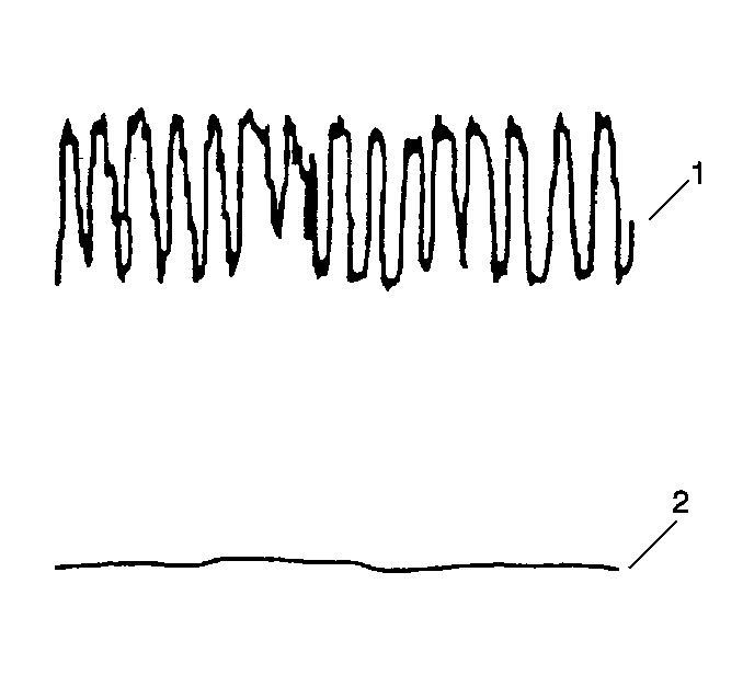
A good TWC catalyst will
show a very active output voltage on the pre-catalyst heated oxygen sensor (1).
A good catalyst, 95 percent hydrocarbon conversion, will show a relatively
flat output voltage on the post-catalyst heated oxygen sensor (2).
Catalyst Monitor (Bad Catalyst)
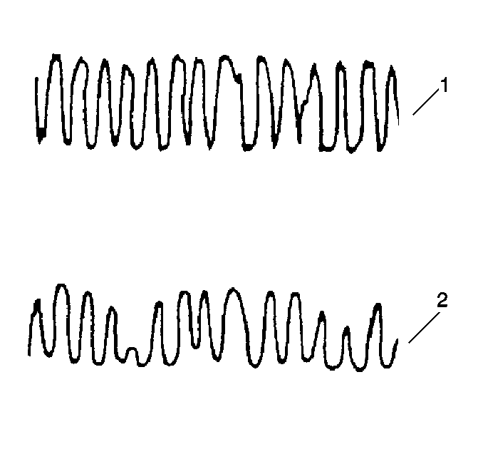
A degraded TWC catalyst,
65 percent hydrocarbon conversion, will show greatly increased activity
in the output voltage from the post-catalyst heated oxygen sensor (2).
The degraded catalyst post-catalyst HO2S output voltage will therefore
appear similar to the typically active output voltage of the pre-catalyst
heated oxygen sensor (1).
Misfire Monitor Diagnostic Operation
The misfire monitor diagnostic is based on crankshaft rotational velocity,
reference period, variations. The powertrain control module determines the
crankshaft rotational velocity using the crankshaft position sensor
and the camshaft position sensor. When a cylinder misfires the crankshaft
actually slows down momentarily. By monitoring the crankshaft and
the camshaft position sensor signals, the control module can calculate
when a misfire occurs.
For a non-catalyst damaging misfire, the diagnostic will be required
to report a misfire that is present within 1000-3200 engine revolutions.
For a catalyst damaging misfire, the diagnostic will respond to a misfire
that is within 200 engine revolutions.
Rough roads may cause a false misfire detection. A rough road will cause
torque to be applied to the drive wheels and the drive train. This torque
can intermittently decrease the crankshaft rotational velocity and
cause a false misfire detection.
On automatic transaxle equipped vehicles, the torque converter clutch
(TCC) will be disabled whenever a misfire is detected. Disabling the TCC isolates
the engine from the rest of the drive line and minimizes the effect
of the drive wheel inputs (torque) on the crankshaft rotation.
When the TCC has been disabled as a result of a misfire detection, the
TCC will be re-enabled after approximately 3200 engine revolutions with no
misfire is detected. The TCC will remain disabled whenever a misfire
is detected. This allows the misfire diagnostic to evaluate the
system.
Fuel Trim System Monitor Diagnostic Operation
The fuel system monitor diagnostic averages of short-term and long-term
fuel trim values. If these fuel trim values stay at the fuel trim limits for
a calibrated period of time, a malfunction is indicated. The fuel
trim diagnostic compares the averages of the short-term fuel trim
values and the long-term fuel trim values to the rich and lean thresholds.
If either value is within the thresholds, a pass is recorded. If
both values are outside the acceptable thresholds, a rich or lean
DTC will be recorded.
In order to meet OBD ll requirements, the control module uses
weighted fuel trim cells in order to determine the need to set a fuel trim
DTC. A fuel trim DTC can only be set if the fuel trim counts in
the weighted fuel trim cells exceed the specifications. A vehicle
that has a fuel trim problem that is causing a concern under certain
conditions but operates fine under other conditions may not set
a fuel trim DTC. For example an engine that is idling high due to
a small vacuum leak or an engine that is running rough due to a
large vacuum leak may set an idle speed DTC or an HO2S DTC but not
a fuel trim DTC.
A fuel trim DTC may be triggered by many different vehicle faults. Use
all of the diagnostic information available when diagnosing a fuel trim fault.
