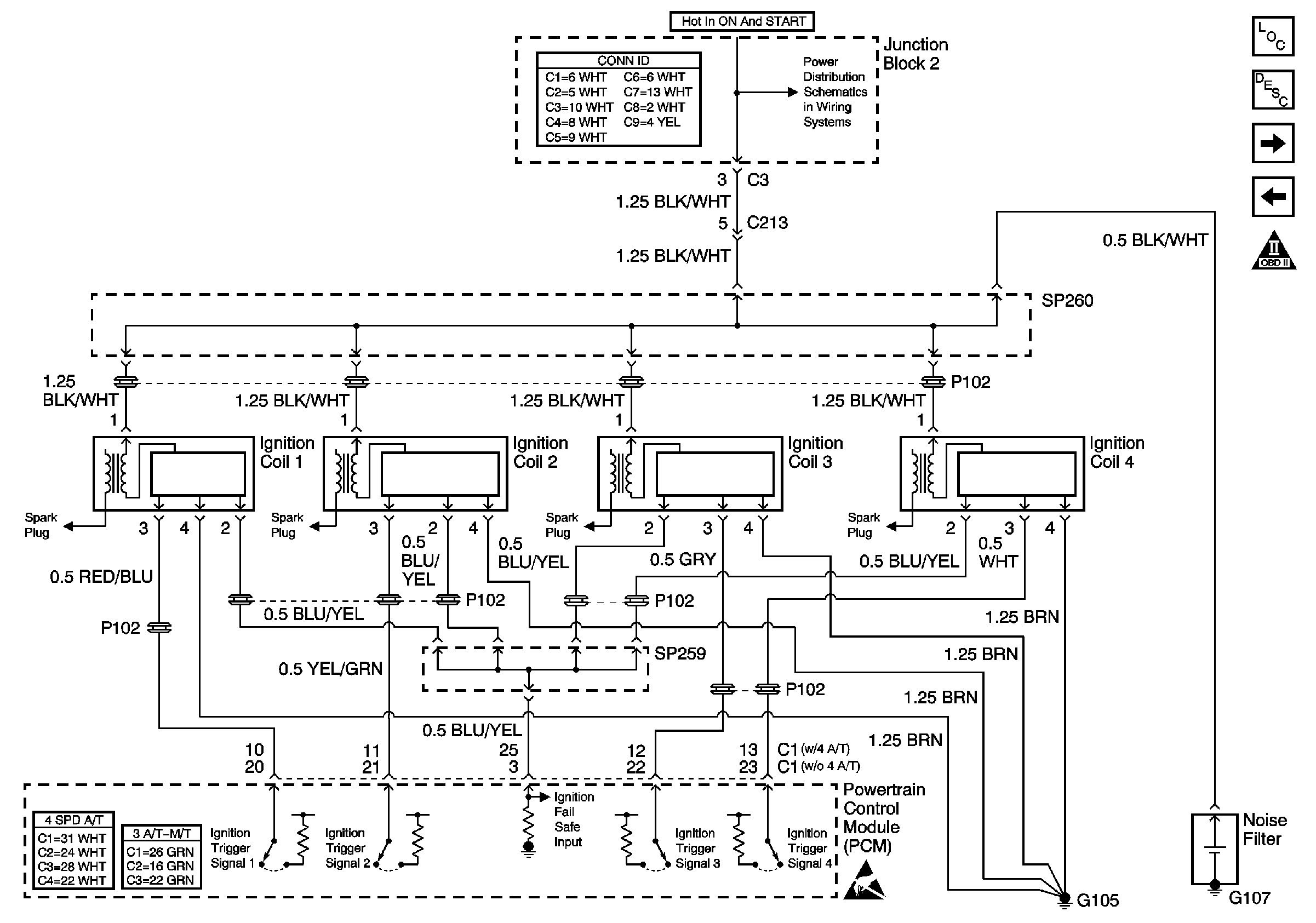
Refer to Engine Controls Schematic
Ignition System
and to
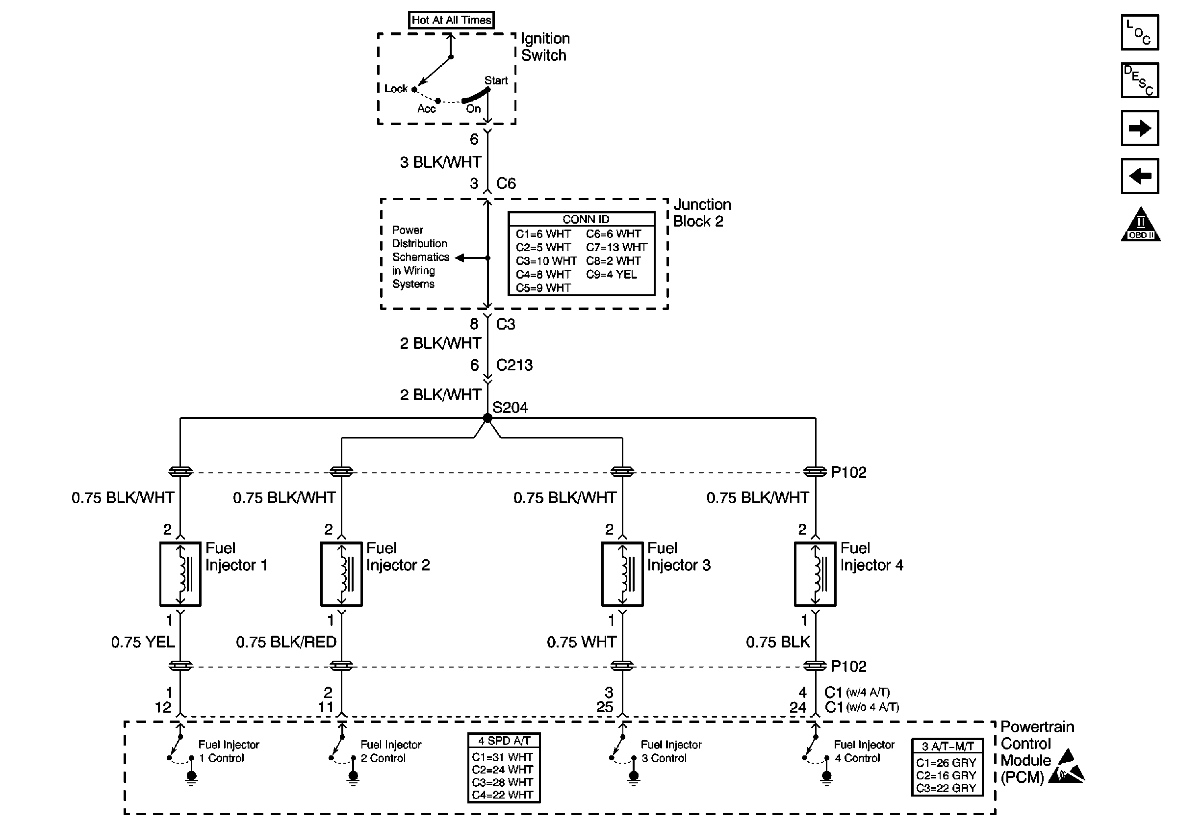
Fuel Injectors
.
Circuit Description
The powertrain control module (PCM) uses the crankshaft position (CKP) sensor and camshaft position (CMP) sensor to determine engine misfire. The CKP sensor and the CMP sensor monitor their respective components and evaluate changes in the crankshaft rotational speed for each cylinder. Irregular changes in the crankshaft rotational speed indicate a possible misfire. The malfunction indicator lamp (MIL) illuminates when the misfire rate equals or exceeds a pre-determined count. A misfire rate that is high enough can cause the catalytic converter to overheat under certain driving conditions. The MIL will flash On and Off when the conditions for catalytic converter overheating are present. Each cylinder is monitored individually for a misfire condition.
Conditions for Running the DTC
| • | The engine speed is between 200 and 4,000 RPM. |
| • | The battery voltage is between 9 volts and 17 volts. |
| • | The engine coolant temperature is between -7°C (20°F) and 123°C (254°F). |
Conditions for Setting the DTC
Misfire is indicated in cylinder 1.
Action Taken When the DTC Sets
| • | The PCM flashes the malfunction indicator lamp (MIL) the first time catalytic converter damage can occur. |
| • | The PCM illuminates the MIL the second time the diagnostic fails. |
| • | The PCM records the operating conditions at the time the diagnostic fails. This information is stored in the Freeze Frame buffer. The PCM also freezes the engine speed at Misfire and the Load at Misfire scan tool data parameters at the time the MIL illuminates. |
Conditions for Clearing the MIL/DTC
| • | The PCM turns OFF the MIL on the third consecutive trip cycle during which the diagnostic has been run and the fault condition is no longer present. |
| • | A DTC will clear after 40 consecutive warm-up cycles have occurred without a fault. |
| • | A DTC can be cleared by using the scan tool Clear DTC Information function. |
Diagnostic Aids
Check for any of the following conditions:
| • | If any DTCs other than misfire (P0300 to P0304) are present, diagnose those DTCs first. |
| • | An intermittent ignition system malfunction may cause DTC P0301 to set. Check the ignition system performance with an engine oscilloscope. |
| • | The engine speed at Misfire and the Load at Misfire scan tool data parameters are fixed at the time the MIL illuminates. These scan tool displays can be used like additional lines of Freeze Frame data. Review the engine speed at Misfire and the Load at Misfire scan tool parameters located on the scan tool Engine Data list. The information can help determine the vehicle conditions when the misfire occurred. |
| • | Review the misfire counters located in the Engine Data list of the scan tool while the engine is running. If the Total Misfire Current data parameter is increasing, the misfire condition is present. A current DTC P0301 should indicate misfire activity in the Misfire Current Cyl #1 parameter. Use this information in order to determine if the fault is present or an intermittent malfunction. |
| • | An intermittent can also be the result of a defective CKP sensor signal rotor. Remove the CKP sensor and inspect the signal rotor through the sensor hole. Check the condition of the signal rotor for nicks, dents, missing teeth, and foreign material. |
| • | Check for engine overheating. |
| • | A MAF sensor output that is incorrect may cause the PCM to command the fuel system to go lean. Check the performance of the MAF sensor. If the HO2S voltage is fixed low, while the fuel trim is constantly high, check the MAF sensor signal circuit for resistance. High circuit resistance can cause the sensor to read a lower volume of air than actual, resulting in a lean fueling condition that can cause engine misfire. |
| • | Check for a PCV system malfunction. Refer to Crankcase Ventilation System Inspection . |
An intermittent malfunction may be caused by a fault in the cylinder 1 ignition system or fuel system electrical circuits. Inspect the wiring harness and the components for an intermittent condition. Refer to Intermittent Conditions .
Repair any electrical circuit faults that were found. Refer to Wiring Repairs in Wiring Systems.
The information included in the Freeze Frame data can be useful in determining the vehicle operating conditions when the DTC first set.
Test Description
The numbers below refer to the step numbers in the diagnostic table.
-
The OBD System Check prompts the technician to complete some basic checks and store the Freeze Frame data on the scan tool if applicable. This creates an electronic copy of the data taken when the fault occurred. The information is then stored in the scan tool for later reference.
-
This step verifies whether the misfire is present. The scan tool will display increasing counts in the Misfire Current Cyl. #1 parameter if a misfire in cylinder 1 is occurring.
-
This step checks whether the DTC P0301 is the result of a hard failure or an intermittent condition. Operating the vehicle in check mode enhances the diagnostic capabilities of the PCM. For additional information on Check mode operation, refer to the Powertrain Control Module Diagnosis. The scan tool will display increasing counts in the Misfire Current Cyl. #1 parameter if a misfire in cylinder 1 is occurring.
-
Fault not present indicates that the condition that caused the DTC P0301 to set is intermittent and not currently present. If no other DTCs are stored, refer to Diagnostic Aids for additional information on diagnosing an intermittent DTC P0301.
-
This step is to verify if the misfire is caused by a fault in the ignition system.
-
Contaminants in the fuel, such as alcohol or water, can create a misfire condition.
-
A vacuum leak can cause a lean misfire condition.
Step | Action | Values | Yes | No | ||||||||||||||||
|---|---|---|---|---|---|---|---|---|---|---|---|---|---|---|---|---|---|---|---|---|
Did you perform the Powertrain On-Board Diagnostic (OBD) System Check? | -- | Go to Step 2 | ||||||||||||||||||
Does the scan tool indicate a misfire in cylinder 1? | -- | Go to Step 5 | Go to Step 3 | |||||||||||||||||
Is DTC P0301 set or does the scan tool indicate a misfire in cylinder 1? | -- | Go to Step 5 | Go to Step 4 | |||||||||||||||||
The fault is not present. Are there any DTCs stored that have not been diagnosed? | -- | Go to Diagnostic Aids | ||||||||||||||||||
Are DTCs P1300, P1305, P1310, or P1315 present? | -- | Go to Step 6 | ||||||||||||||||||
6 |
Was a crisp, blue spark present on every engine revolution? | -- | Go to Step 8 | Go to Step 7 | ||||||||||||||||
7 |
Did the test indicate a crisp, blue spark while cranking the engine? | -- | Go to Step 15 | Go to Step 16 | ||||||||||||||||
8 |
Was a repair necessary? | -- | Go to Step 18 | Go to Step 9 | ||||||||||||||||
9 |
Was a faulty spark plug condition found and repaired? | -- | Go to Step 18 | Go to Step 10 | ||||||||||||||||
10 |
Does the injector test lamp blink while cranking the engine? | -- | Go to Step 11 | |||||||||||||||||
11 | Perform the Fuel Injector Coil Test and the Fuel Injector Balance Test procedures. Refer to Fuel Injector Solenoid Coil Test - Engine Coolant Temperature Between 10-35 Degrees C (50-95 Degrees F) and to Fuel Injector Balance Test . Did any fuel injectors require replacement? | -- | Go to Step 18 | Go to Step 12 | ||||||||||||||||
12 |
Is the fuel pressure within the specified range? | 301-347 kPa (44-50 psi) | Go to Step 13 | Go to Fuel System Diagnosis | ||||||||||||||||
Was a repair necessary? | -- | Go to Step 18 | Go to Step 14 | |||||||||||||||||
Was a repair necessary? | -- | Go to Step 18 | Go to Step 17 | |||||||||||||||||
15 | Replace the ignition coil 1. Refer to Ignition Coil Replacement . Is the action complete? | -- | Go to Step 18 | -- | ||||||||||||||||
16 |
Is the action complete? | -- | Go to Step 18 | -- | ||||||||||||||||
17 |
Was a basic engine mechanical concern found and repaired? | -- | Go to Step 18 | Go to Diagnostic Aids | ||||||||||||||||
18 |
Did a DTC set or did the scan tool indicate a misfire in cylinder 1? | -- | System OK |
