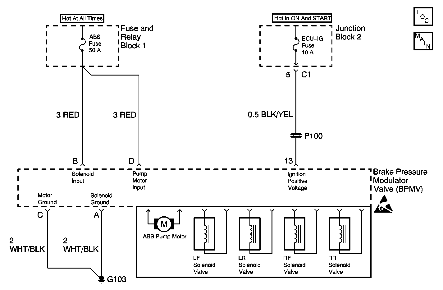
Circuit Description
The Electronic Brake Control Module (EBCM) monitors available voltage level at terminal B.
Conditions for Setting the DTC
This DTC will set if the voltage level at terminal 13 or terminal B is less than 8 volts.
Action Taken When the DTC Sets
| • | A malfunction DTC stores |
| • | The ABS disables |
| • | The ABS warning indicator turns ON |
Conditions for Clearing the DTC
The condition responsible for setting the DTC no longer exists and the Scan Tool Clear DTCs function is used.
Diagnostic Aids
Inspect for the following when diagnosing this part of the Antilock Brake System (ABS):
| • | Vehicle charging system is not operating properly (low generator output or faulty battery) |
| • | High resistance in the ignition power circuit (Terminal 13) or the solenoid power input circuit (Terminal B) |
| • | Poor G103 |
An intermittent malfunction is most likely caused by a poor connection rubbed through wire insulation or a wire that is broken inside the insulation.
Inspect the harness connectors for the following conditions:
| • | Backed-out terminals |
| • | Improper mating |
| • | Broken locks |
| • | Improperly formed or damaged terminals |
| • | Poor terminal to wiring connections |
Test Description
The number(s) below refer to the step number(s) on the diagnostic table.
-
Tests for proper generator output of the vehicle charging system.
-
Tests for high resistance in the solenoid power input circuit.
-
Tests for high resistance in the ground circuit.
-
Tests for high resistance in the ignition power input circuit.
-
Determines whether the condition is present during an ABS stop.
Step | Action | Value(s) | Yes | No |
|---|---|---|---|---|
1 | Was the Diagnostic System Check performed? | -- | Go to Step 2 | |
Test the vehicles charging system. Refer to Charging System in Engine Electrical. Is the vehicle's charging system output below specifications? | -- | Go to Step 7 | Go to Step 3 | |
Is the resistance within the specified range? | 0-2 ohms | Go to Step 4 | Go to Step 8 | |
Use J 39200 (DMM) in order to measure the resistance between the EBCM electrical connector terminal A (harness side) and ground. s the resistance within the specified range? | 0-2 ohms | Go to Step 5 | Go to Step 12 | |
Is the resistance within the specified range? | 0-2 ohms | Go to Step 6 | Go to Step 9 | |
Is DTC C0899 set as a Current DTC? | -- | Go to Step 10 | Go to Step 11 | |
7 | Repair the vehicle's charging system. Refer to Charging System in Engine Electrical. Is the repair complete? | -- | -- | |
8 | Repair the open or high resistance in the RED wire between the EBCM terminal B and the ABS Fuse. Refer to Wiring Repairs in Wiring Systems. Is the repair complete? | -- | -- | |
9 | Repair the open or high resistance in the BLK/YEL wire. Refer to Wiring Repairs in Wiring Systems. Is the repair complete? | -- | -- | |
10 |
Is the repair complete? | -- | -- | |
11 | A malfunction is not present at this time. Refer to Diagnostic Aids for additional information regarding this DTC. Is the action complete? | -- | -- | |
12 | Repair the open or high resistance in the WHT/BLK wire between the EBCM connector terminal A and G103. Refer to Wiring Repairs in Wiring Systems. Is the repair complete? | -- | -- |
