Circuit Description
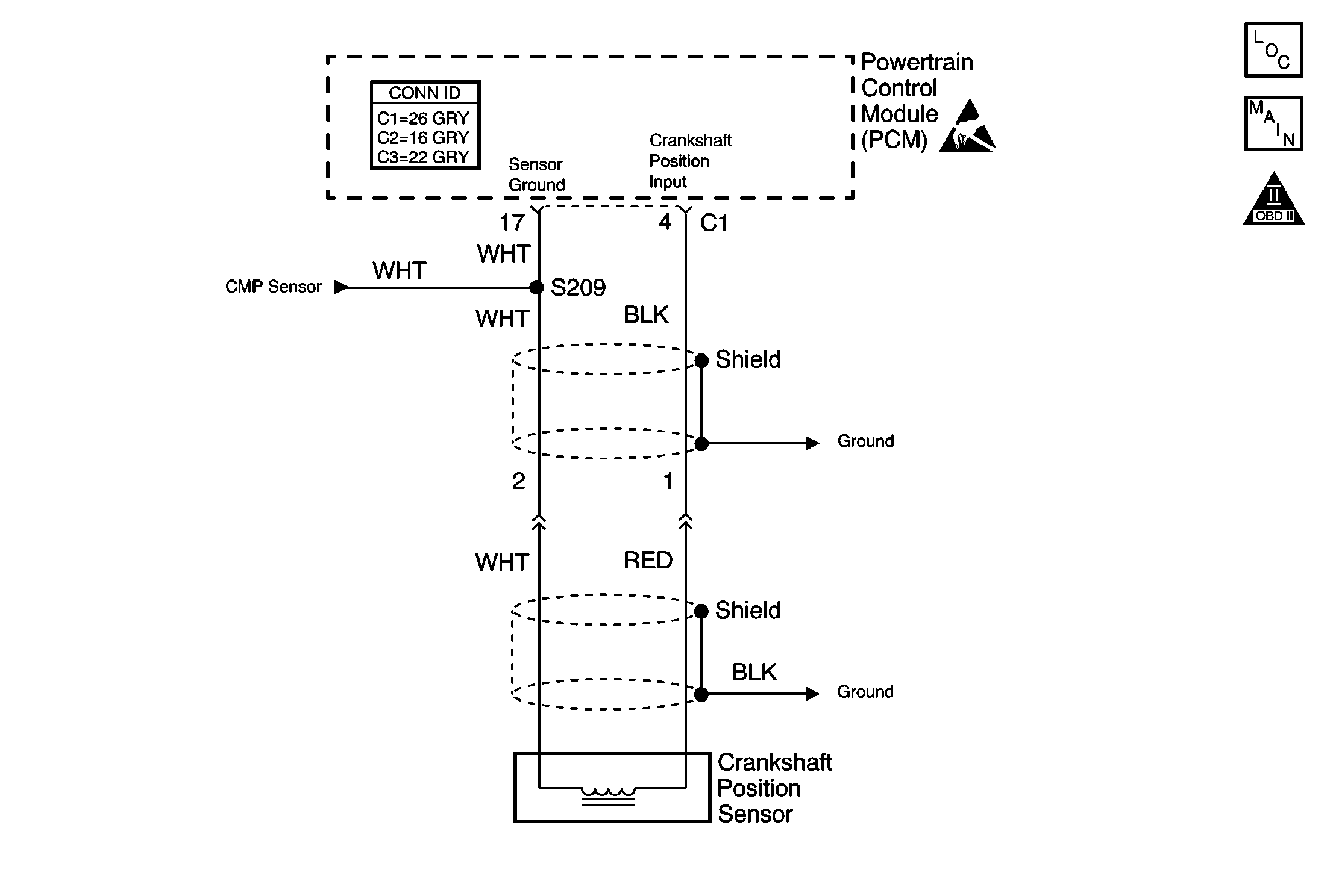
The crankshaft position (CKP) sensor is a magnetic generator type sensor, producing an alternating current signal. The CKP sensor signal increases in both frequency and amplitude as the engine RPM increases. The CKP sensor sends this reference signal to the powertrain control module (PCM) to indicate crankshaft RPM and position. This reference signal is used by the PCM to calculate fuel injection pulse, establish top dead center for ignition timing and where to start ignition coil and injection sequencing. There will be no spark or fuel delivery if there is no CKP sensor signal.
Conditions for Setting the DTC
No crankshaft position sensor signal to the PCM for 5 seconds while cranking. The PCM must also see the crank signal on terminal C3-11 in order to run this diagnostic.
OR
No crankshaft position sensor signal to PCM with engine speed at 600 RPM or more.
Action Taken When the DTC Sets
| • | The PCM illuminates the MIL during the second key cycle in which the DTC sets. |
| • | The PCM stores the conditions which were present when the DTC set as Freeze Frame Data. |
Conditions for Clearing the MIL/DTC
| • | The PCM turns OFF the MIL on the third consecutive trip cycle during which the diagnostic has been run and the fault condition is no longer present. |
| • | A DTC will clear after 40 consecutive warm-up cycles have occurred without a fault. |
| • | A DTC can be cleared by using the scan tool Clear DTC Information function. |
Diagnostic Aids
Check for any of the following conditions:
| • | The scan tool will display engine speed while cranking if the PCM is seeing the CKP sensor signal. |
| • | The CKP sensor performance may be affected by temperature. Check the sensor's operation and internal resistance at various temperatures. The CKP sensor resistance when COLD should be between 1,630 ohms and 2,740 ohms at -10° to 50°C (14°-122°F). The CKP sensor resistance when HOT should be between 2,065 ohms and 3,225 ohms at 50°-100°C (122°-212°F). |
| • | An intermittent DTC P0335 can be caused by a defective signal rotor. Remove the CKP sensor and visually inspect the teeth of the signal rotor through the CKP sensor aperture for damage, foreign material, or incorrect installation. |
| • | A DTC P0335 that sets while driving and checks OK may be caused by inadequate CKP sensor circuit shielding. Check that the CKP sensor circuit is properly shielded and that the drain wire is fastened securely to ground. |
An intermittent malfunction may be caused by a fault in the CKP sensor electrical circuit. Inspect the wiring harness and components for any of the following conditions:
| • | Backed out terminals. |
| • | Improper mating of terminals. |
| • | Broken electrical connectors locks. |
| • | Improperly formed or damaged terminals |
| • | Faulty terminal to wire connections. |
| • | Physical damage to the wiring harness. |
| • | A broken wire inside the insulation. |
| • | Corrosion of electrical connections, splices, or terminals. |
Repair any electrical circuit faults that were found. Refer to Wiring Repairs in Wiring Systems.
The information included in the Freeze Frame data can be useful in determining the vehicle operating conditions when the DTC first set.
Test Description
The numbers below refer to the step numbers in the Diagnostic Table.
-
The OBD System Check prompts the technician to complete some basic checks and store the freeze frame data on the scan tool if applicable. This creates an electronic copy of the data taken when the fault occurred. The information is then stored in the scan tool for later reference.
-
This step checks whether DTC P0335 is the result of a hard failure or an intermittent condition. If engine will not start, crank engine over 3 consecutive ignition cycles (key ON -- key OFF).
-
This step is checking the internal resistance of the crankshaft position sensor. A typical value at 23°C (74°F) is 2.1k ohms.
-
This step checks the CKP sensor output signal.
-
This step checks the CKP sensor electrical circuit to the PCM. The DMM should read the CKP sensor output signal of 1.4-1.6 volts AC when cranking.
-
This step checks the CKP sensor input circuit.
-
This step checks for a faulty signal rotor. Visually inspect the teeth of the signal rotor through the CKP sensor aperture for damage, foreign material, and mis-alignment.
Step | Action | Value(s) | Yes | No | ||||||
|---|---|---|---|---|---|---|---|---|---|---|
Did you perform the Powertrain On-Board Diagnostic (OBD) System Check? | -- | |||||||||
2 | Are a DTC P0335 and a DTC P0340 both set? | -- | ||||||||
Does the vehicle start and run? | -- | |||||||||
4 |
Is a DTC P0335 set? | -- | Fault Not Present-Go to Diagnostic Aids | |||||||
Is the CKP sensor resistance within the specified value? | 1,630-2,740 ohms at -10°C to 50°C (14°-122°F) or 2,065-3,225 ohms at 50°-100°C (122°F-212°F) | |||||||||
Was the AC voltage indicated while cranking within the specified value? | 1.4-1.6 volts AC | |||||||||
Was the AC voltage indicated while cranking within the specified value? | 1.4-1.6 volts AC | |||||||||
Was the AC voltage indicated while cranking within the specified value? | 0.9-1.1 volts AC | |||||||||
9 | Repair the open or the short in the CKP input circuit. Refer to Wiring Repairs in Wiring Systems. Is the action complete? | -- | -- | |||||||
10 | Repair the open in the CKP sensor ground circuit. Refer to Wiring Repairs in Wiring Systems. Is the action complete? | -- | -- | |||||||
11 | Repair the open in the CKP and CMP sensors ground circuit between splice S209 and the PCM. Refer to Wiring Repairs in Wiring Systems. Is the action complete? | -- | -- | |||||||
Was a repair necessary? | -- | |||||||||
13 | Replace the Crankshaft Position sensor. Refer to Crankshaft Position Sensor Replacement . Is the action complete? | -- | -- | |||||||
14 | Replace the PCM. Refer to Powertrain Control Module Replacement . Is the action complete? | -- | -- | |||||||
15 |
Are any DTCs displayed on scan tool? | -- | Go to the applicable DTC table | System OK |
