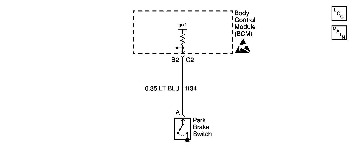
Circuit Description
The park brake switch is a discrete input to the body control module (BCM). When the park brake is applied, the park brake switch grounds the park brake switch input to the BCM (circuit 1134).
Conditions for Running the DTC
| • | The ignition switch is on. |
| • | The vehicle speed is above 8 Kph (5 Mph). |
Conditions for Setting the DTC
The park brake switch input to the BCM is grounded for 2 seconds
Action Taken When the DTC Sets
The park brake chime sounds until the vehicle speed is reduced or the park brake switch is released.
Conditions for Clearing the DTC
| • | A current DTC B0005 will clear when the vehicle speed is reduced or the park brake switch is released. |
| • | All BCM history codes clear after 100 ignition cycles with no current codes active during th 100 ignition cycles. |
| • | Use the Scan Tool. |
Test Description
The number(s) below refer to the step number(s) on the diagnostic table.
-
The normal state of the PARK BRAKE SWITCH parameter is OFF with the park brake unapplied.
-
The normal state of the PARK BRAKE SWITCH parameter is ON with the park brake applied.
-
The normal state of the PARK BRAKE SWITCH parameter is OFF with the park brake switch disconnected.
Step | Action | Yes | No |
|---|---|---|---|
1 | Did you perform the Hydraulic Brakes Diagnostic System Check? | Go to Step 2 | Go to A Diagnostic System Check-Hydraulic Brakes |
Does the scan tool display OFF? | Go to Step 3 | Go to Step 4 | |
Does the PARK BRAKE SWITCH parameter change state? | Go to Diagnostic Aids | Go to Step 4 | |
Does the scan tool display OFF? | Go to Step 7 | Go to Step 5 | |
5 | Test the signal circuit of the park brake switch for a short to ground. Refer to Circuit Testing and Wiring Repairs in Wiring Systems. Did you find and correct the condition? | Go to Step 10 | Go to Step 6 |
6 | Inspect for poor connections at the harness connector of the BCM. Refer to Testing for Intermittent and Poor Connections and Connector Repairs in Wiring Systems. Did you find and correct the condition? | Go to Step 10 | Go to Step 8 |
7 | Inspect for poor connections at the harness connector of the park brake switch. Refer to Testing for Intermittent and Poor Connections and Connector Repairs in Wiring Systems. Did you find and correct the condition? | Go to Step 10 | Go to Step 9 |
8 | Replace the BCM. Refer to Body Control Module Replacement in Body Control System. Important: Perform the set up procedure for the BCM. Refer to BCM Programming/RPO Configuration in Body Control System. Did you complete the replacement? | Go to Step 10 | -- |
9 | Replace the park brake switch. Refer to Park Brake Switch Replacement in Park Brakes. Did you complete the replacement? | Go to Step 10 | -- |
10 |
Does the DTC reset? | Go to Step 2 | System OK |
