Special Tools
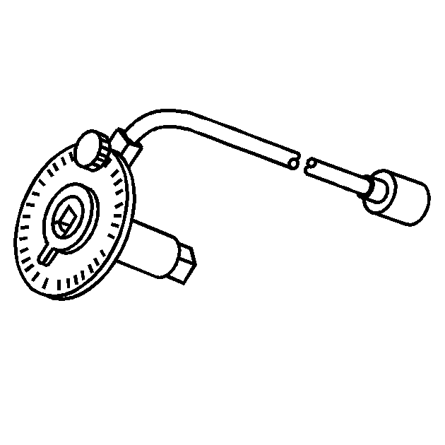
| • | J 42492-A (KM-421-A) Timing Belt Adjuster |
| • | J 45059 Angle Meter |
| • | KM-470-B Angular Torque Gage |
Removal Procedure
- Remove the fuel pump fuse.
- Start the engine. After it stalls, crank the engine for 10 seconds to rid the fuel system of fuel pressure.
- Disconnect the negative battery cable.
- Disconnect the electronic control module (ECM) ground terminal from the intake manifold.
- Drain the engine coolant. Refer to Cooling System Draining and Filling .
- Drain the engine oil.
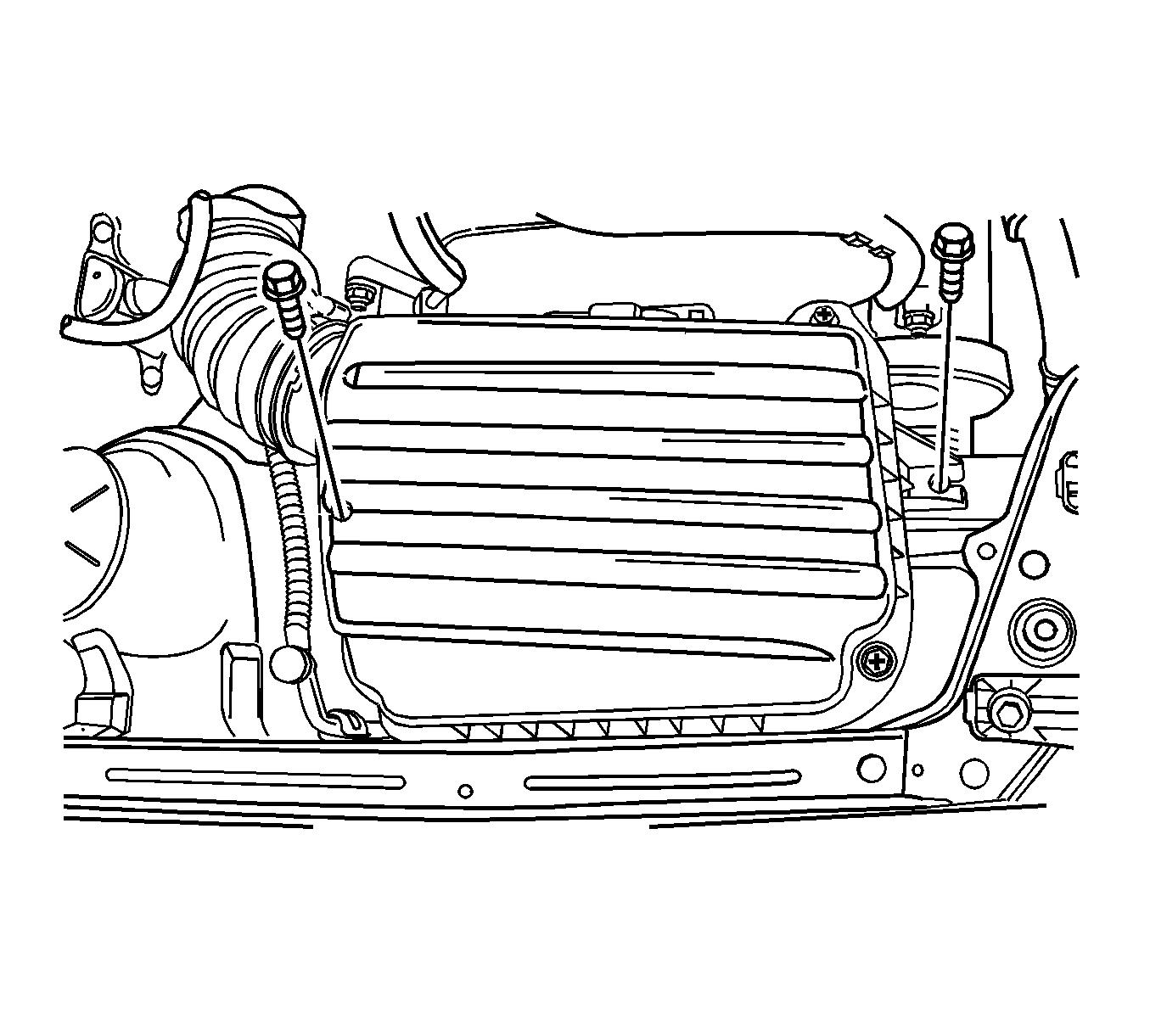
- Remove the air cleaner housing.
- Remove the throttle cable and inlet/outlet coolant hoses.
- Remove the thermostat upper hose.
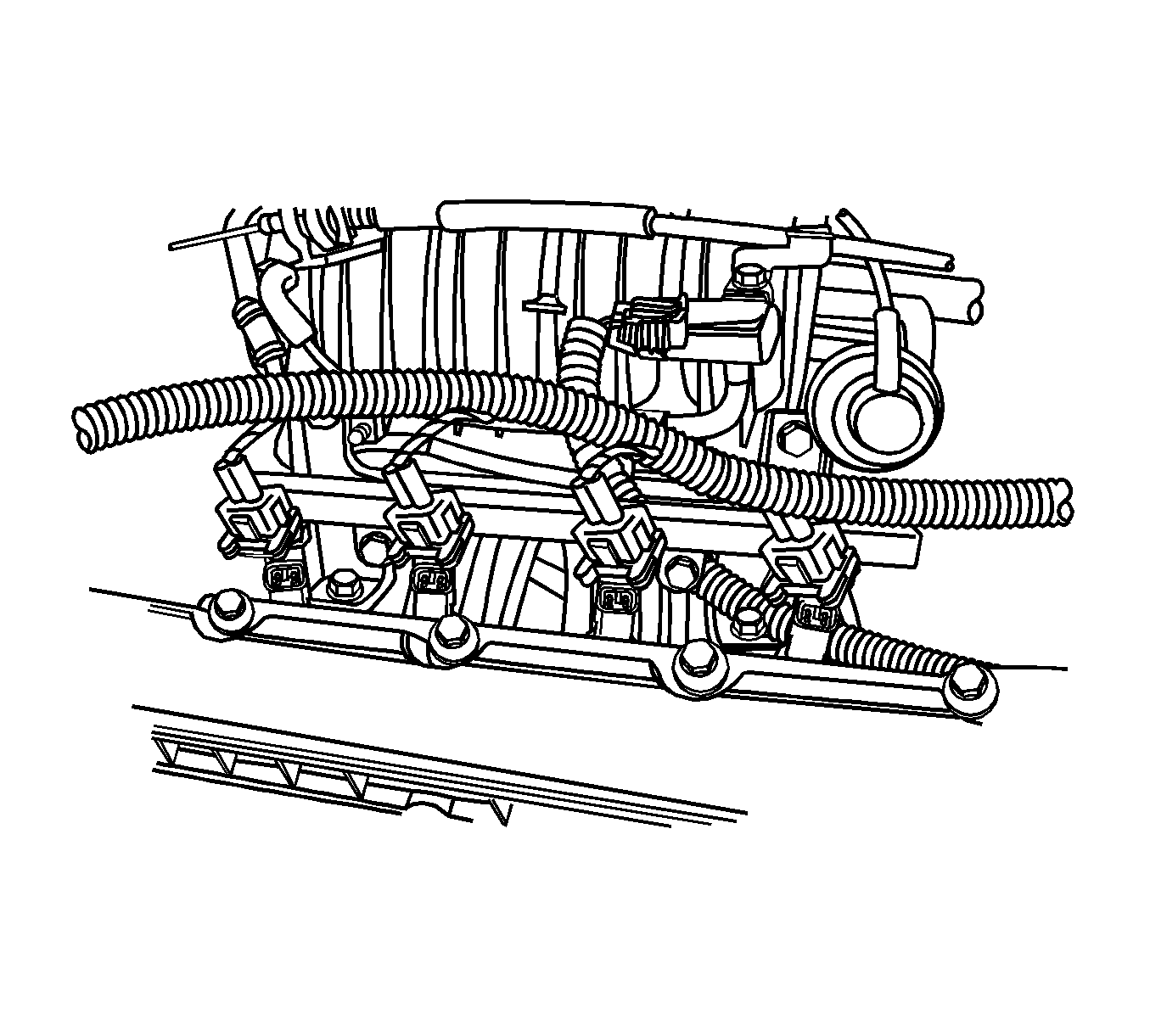
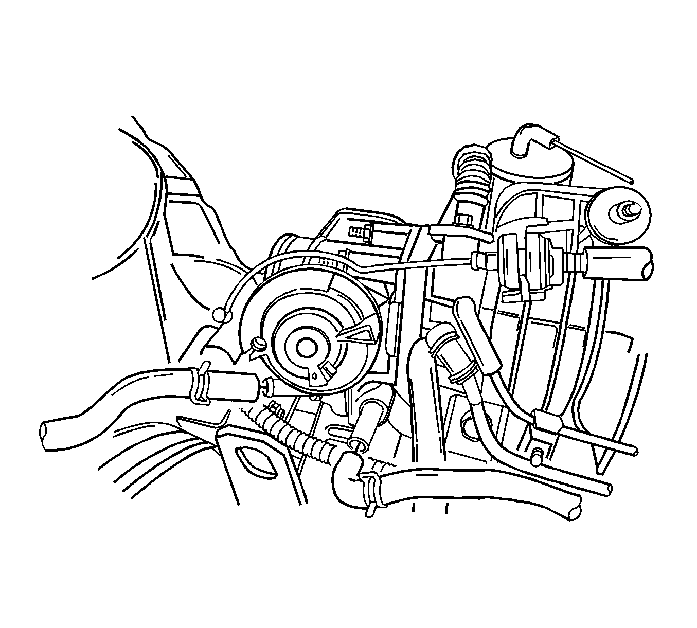
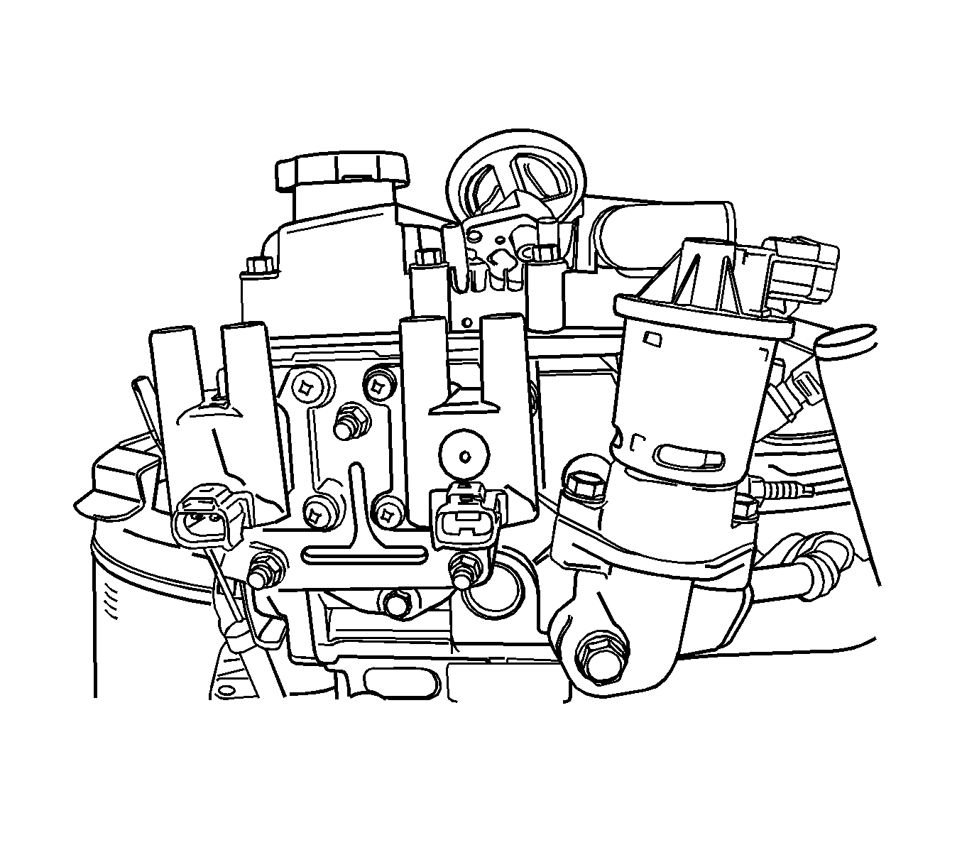
- Remove the intake manifold pressure sensor, intake air temperature sensor and coolant temperature sensor.
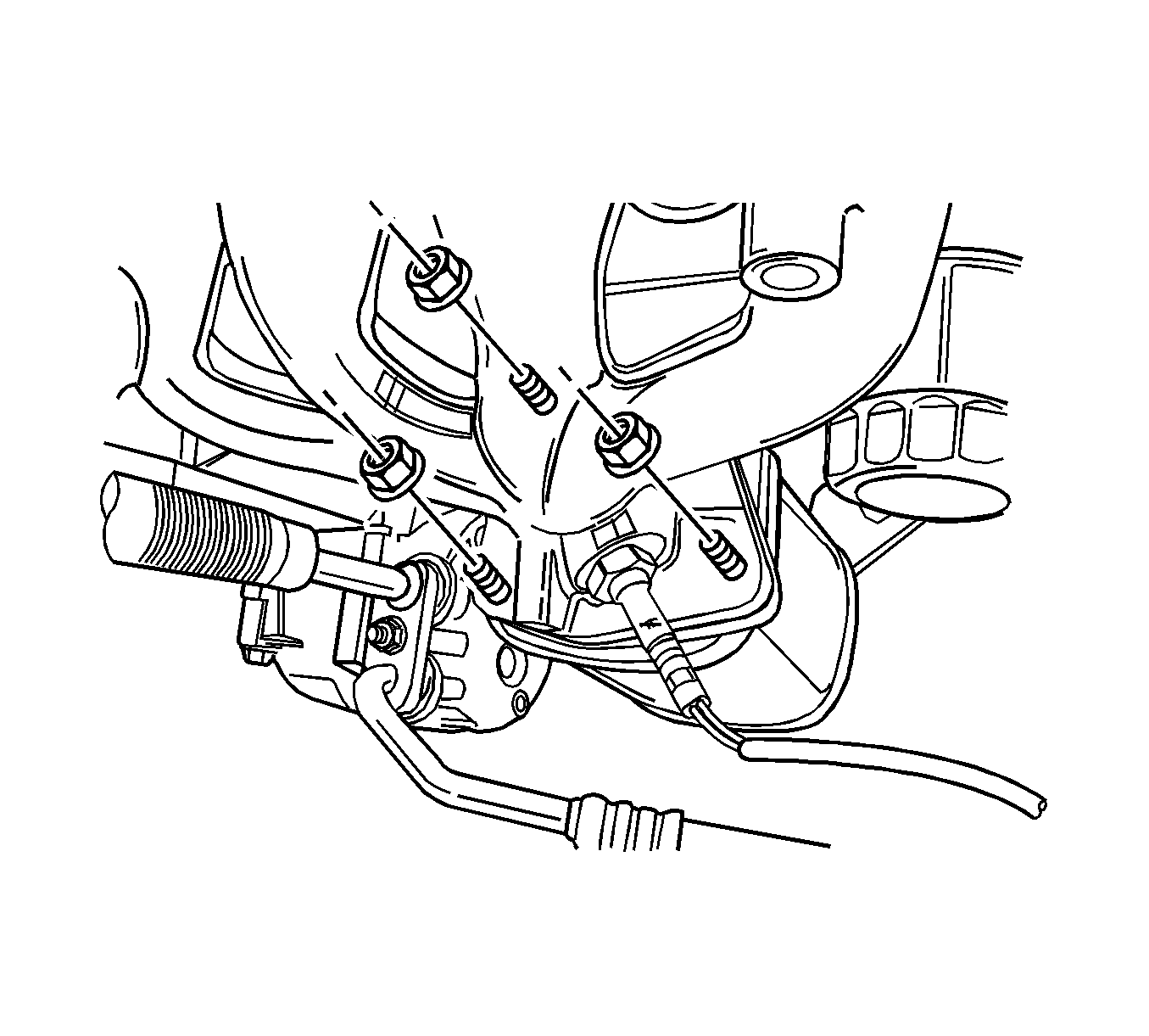
- Remove the intake manifold support bracket.
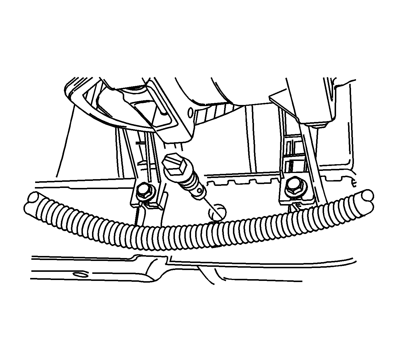
- Remove the all the vacuum hoses from the intake manifold including brake booster vacuum hose.
- Remove the ignition cables from the spark plugs.
- Remove the direct ignition coil and the bracket from the cylinder head.
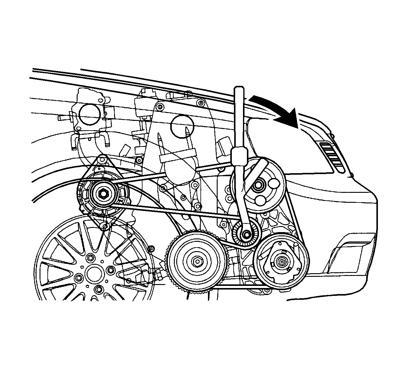
- Remove the serpentine accessory drive belt. Refer to Power Steering Pump Belt Replacement .
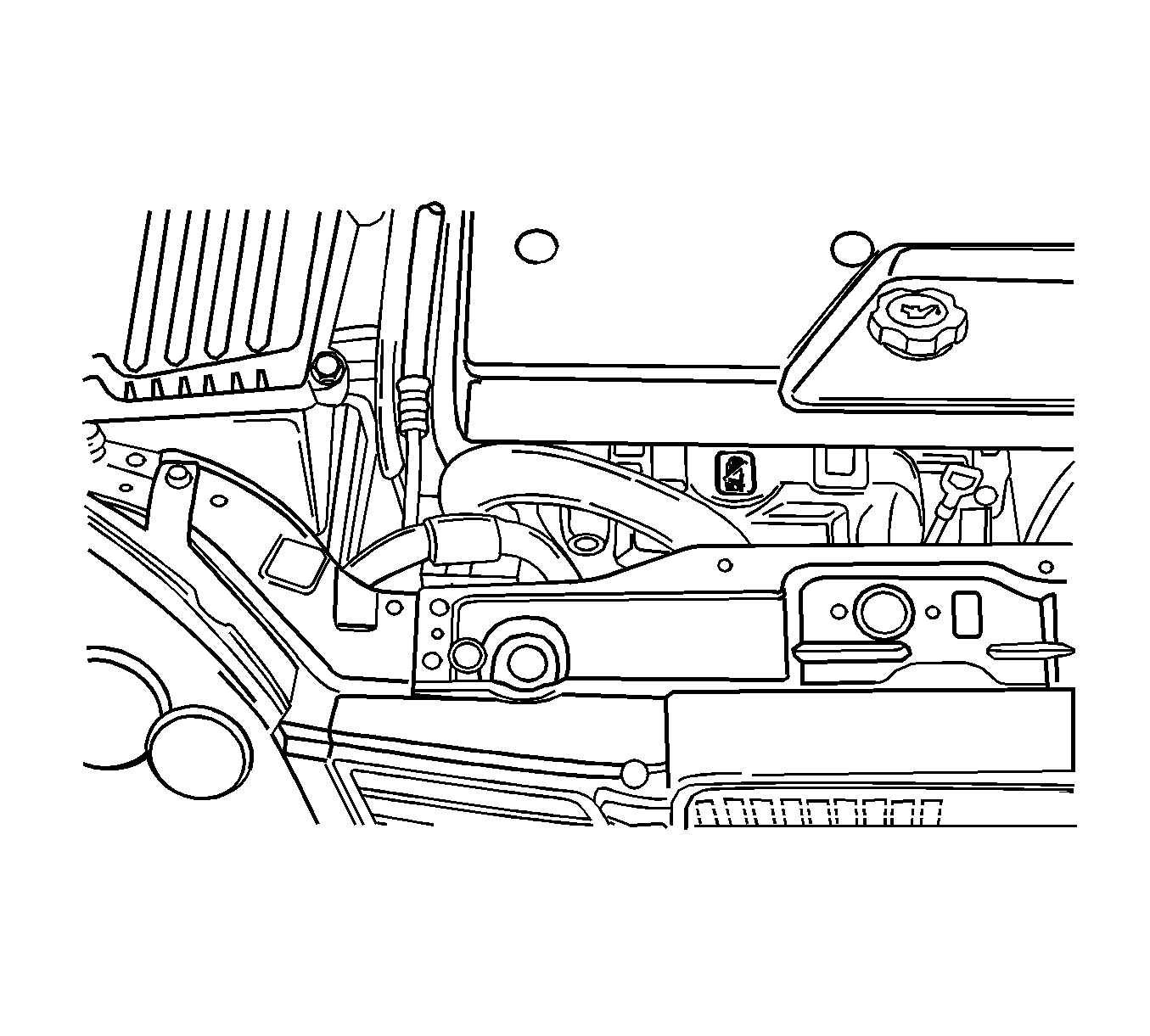
- Remove the front passenger side tire. Refer to Tire and Wheel Removal and Installation .
- Remove the front wheel housing shield.
- Remove the upper front timing belt cover bolts.
- Remove the upper front timing belt cover.
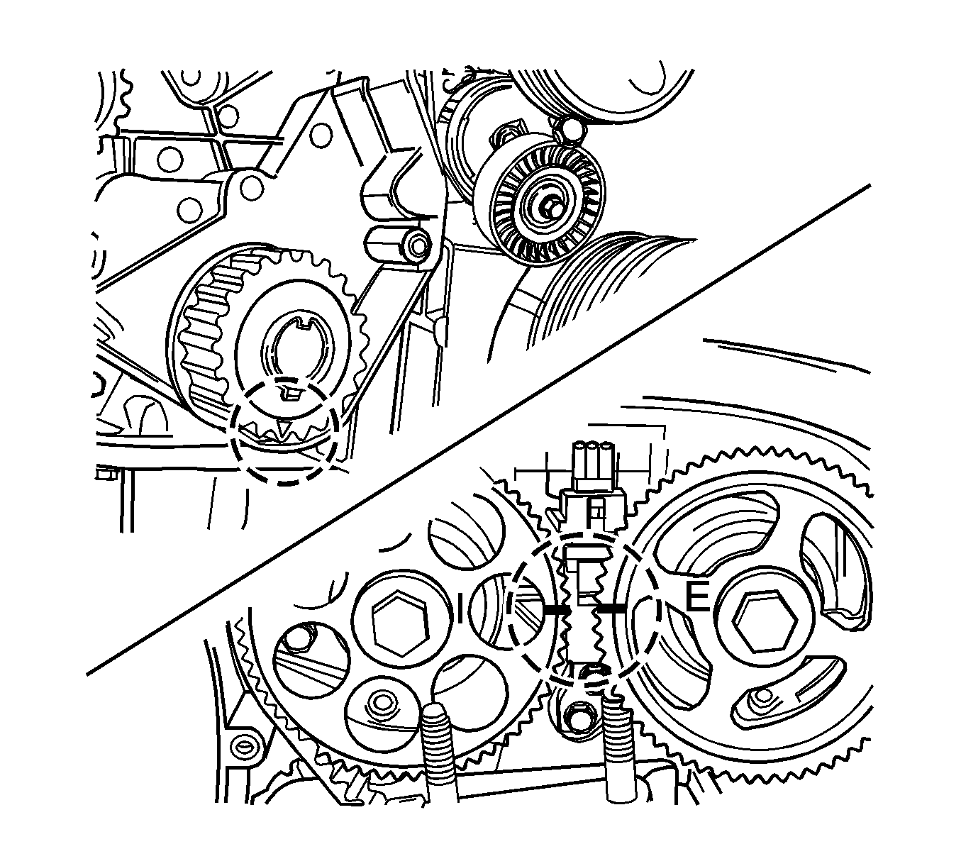
- Align the camshaft gear timing marks.
- Remove the crank shaft pulley.
- Remove the lower front timing belt cover bolts and cover.
- Slightly loosen the water pump retaining bolts.
- Rotate the water pump counterclockwise using J 42492-A to relieve the timing belt tension.
- Remove the timing belt. Refer to Timing Belt Replacement .
- Remove the engine mounting bracket. Refer to Engine Mount Replacement .
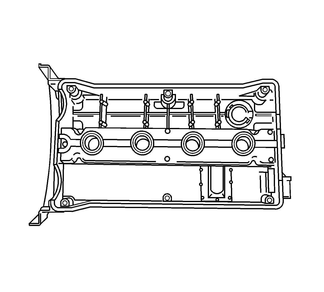
- Remove the camshaft cover. Refer to Valve Rocker Arm Cover Replacement .
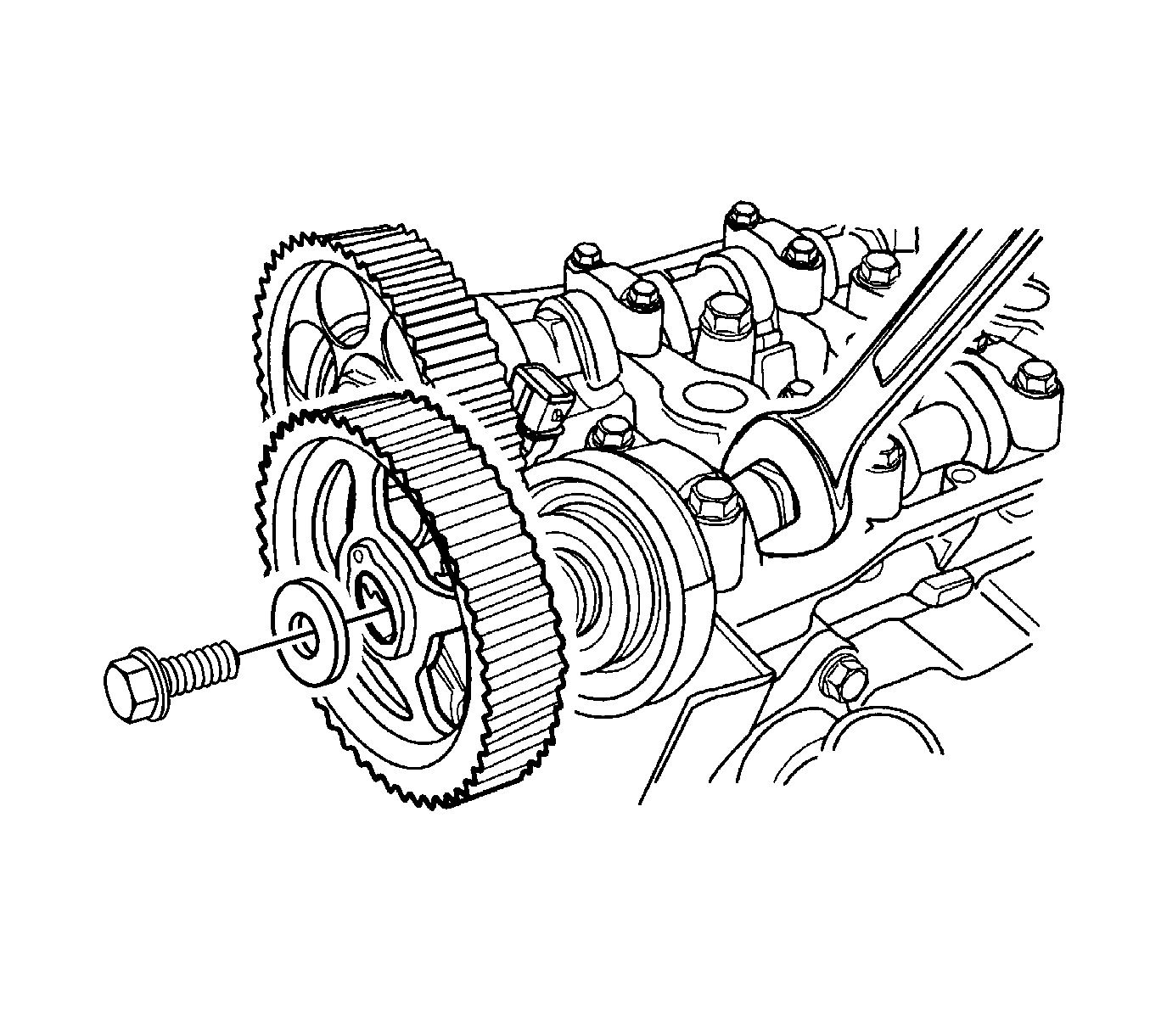
- While holding the intake camshaft firmly in place, remove the intake camshaft gear bolt and gear.
- While holding the exhaust camshaft firmly in place, remove the exhaust camshaft gear bolt and gear.
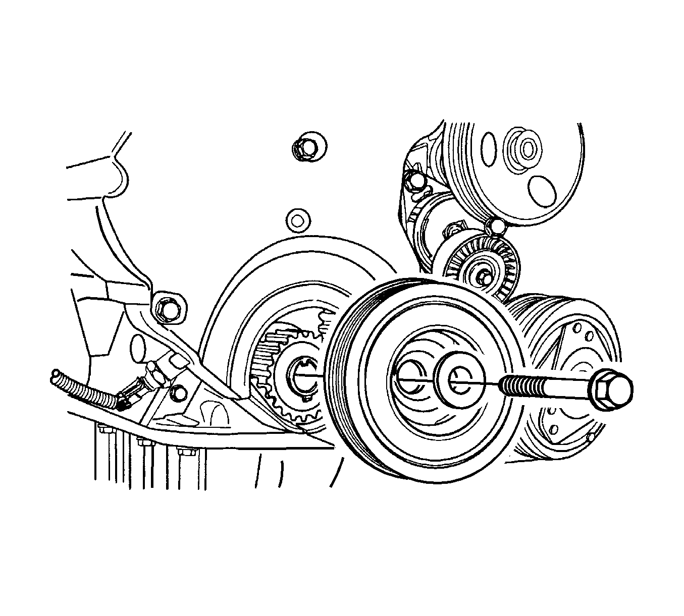
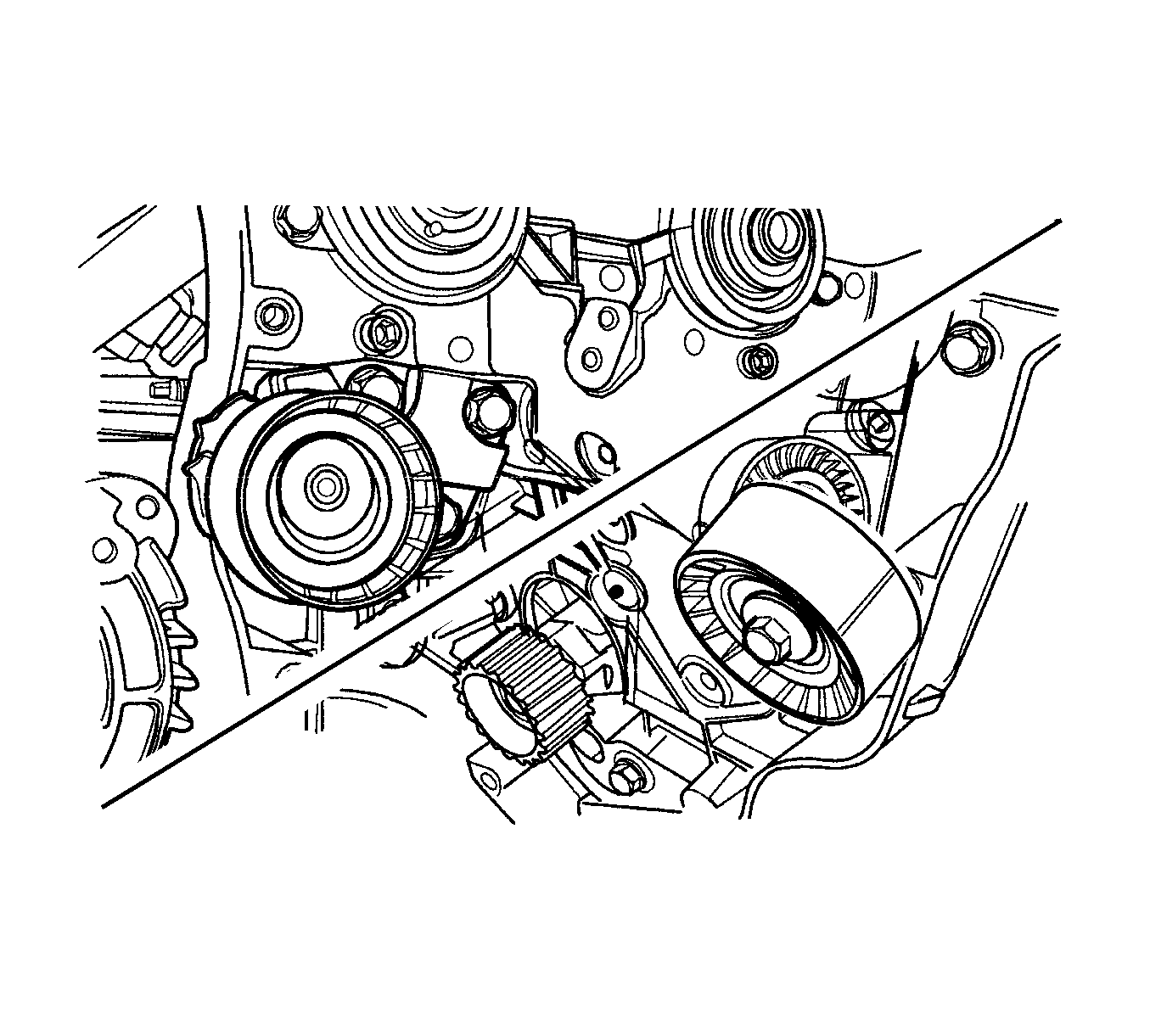
- Remove the timing belt automatic tensioner.
- Remove the timing belt idler pulley.
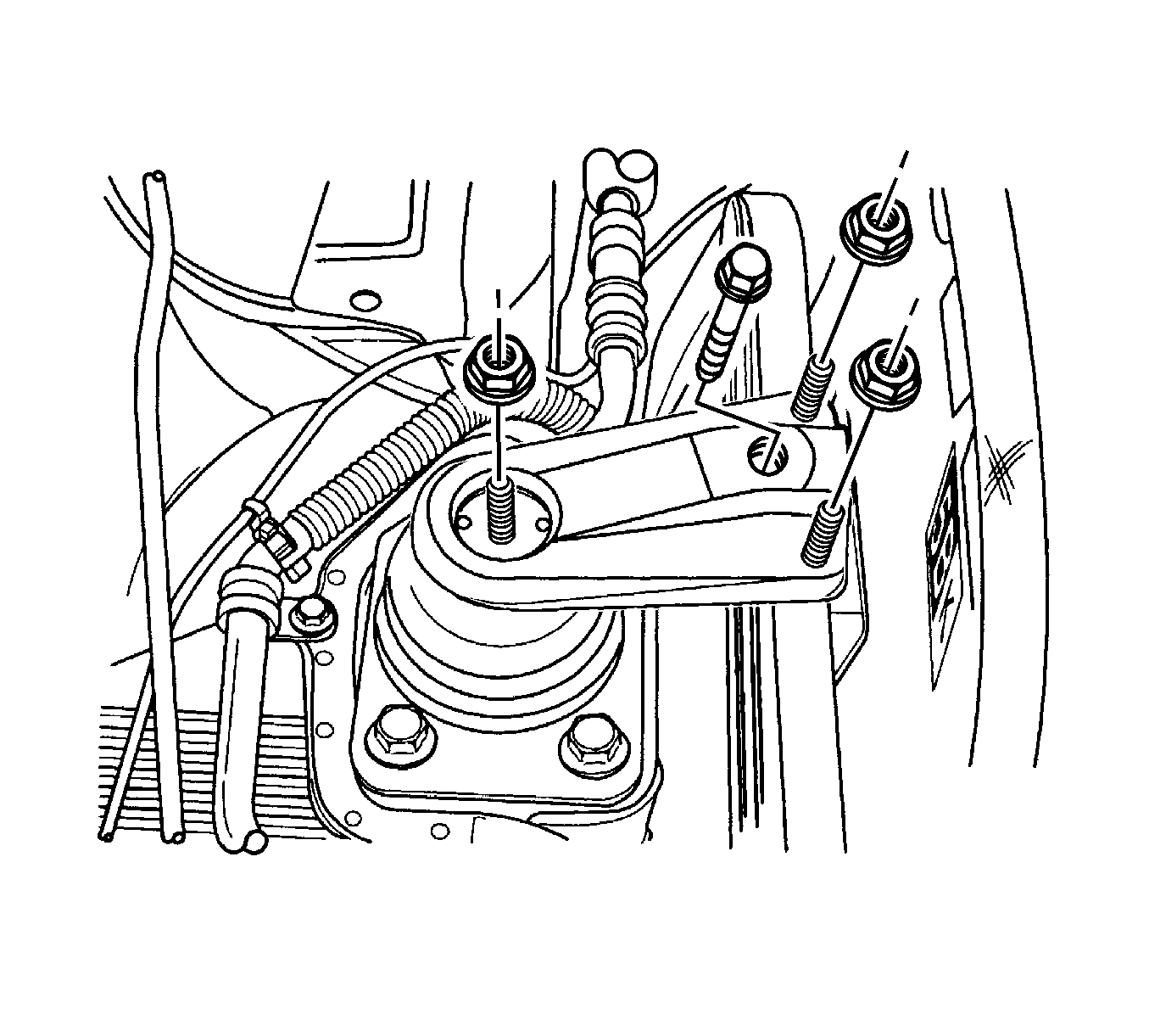
- Remove the right engine mount. Refer to Engine Mount Replacement .
- Remove the rear timing belt cover.
- Remove the intake and exhaust manifold. Refer to Intake Manifold Replacement and Exhaust Manifold Removal .
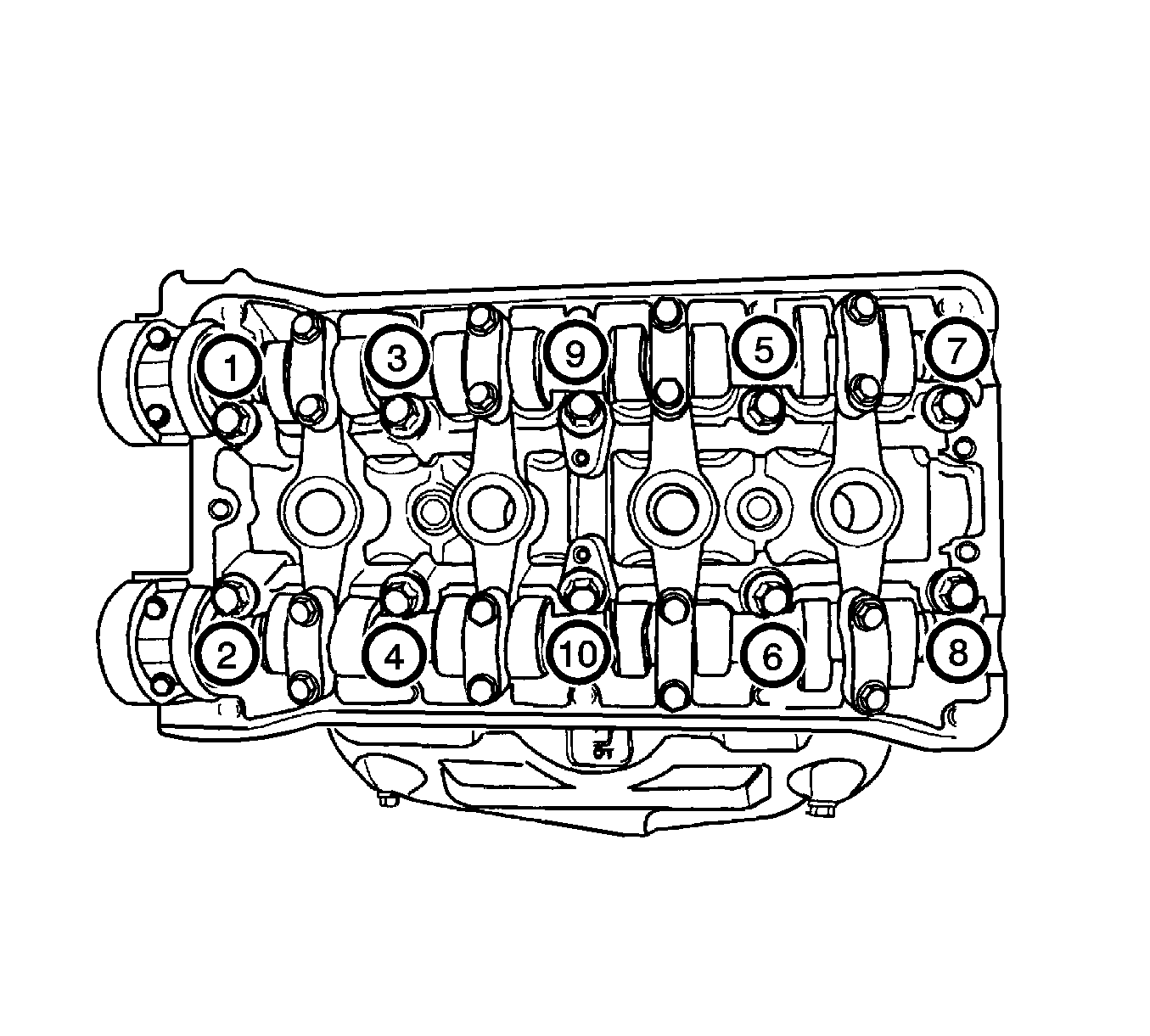
- Remove the cylinder head bolts gradually in the sequence shown and remove the cylinder head.
- Remove the cylinder head gasket.
- Clean the gasket surfaces on the cylinder head and the engine block. Refer to Cylinder Head Cleaning and Inspection .
Caution: Refer to Battery Disconnect Caution in the Preface section.
Important: Take extreme care to prevent any scratches, nicks or damage to the camshafts.
Notice: Use extreme care when removing the cylinder head to prevent any engine oil , dirt, or coolant from entering the engine. Damage to the engine could result.
Installation Procedure
- Install the new cylinder head gasket.
- Install the intake/exhaust manifold to the cylinder head. Refer to Intake Manifold Replacement and Exhaust Manifold Removal .
- Install the cylinder head bolts gradually in the sequence shown using J 45059 or KM-470-B .
- Install the right engine mount. Refer to Engine Mount Replacement .
- Connect the throttle cable at the throttle body and the intake manifold.
- Install the intake manifold support bracket upper bolts to the intake manifold.
- Connect the surge tank coolant hose at the throttle body.
- Connect the heater inlet hose to the cylinder head.
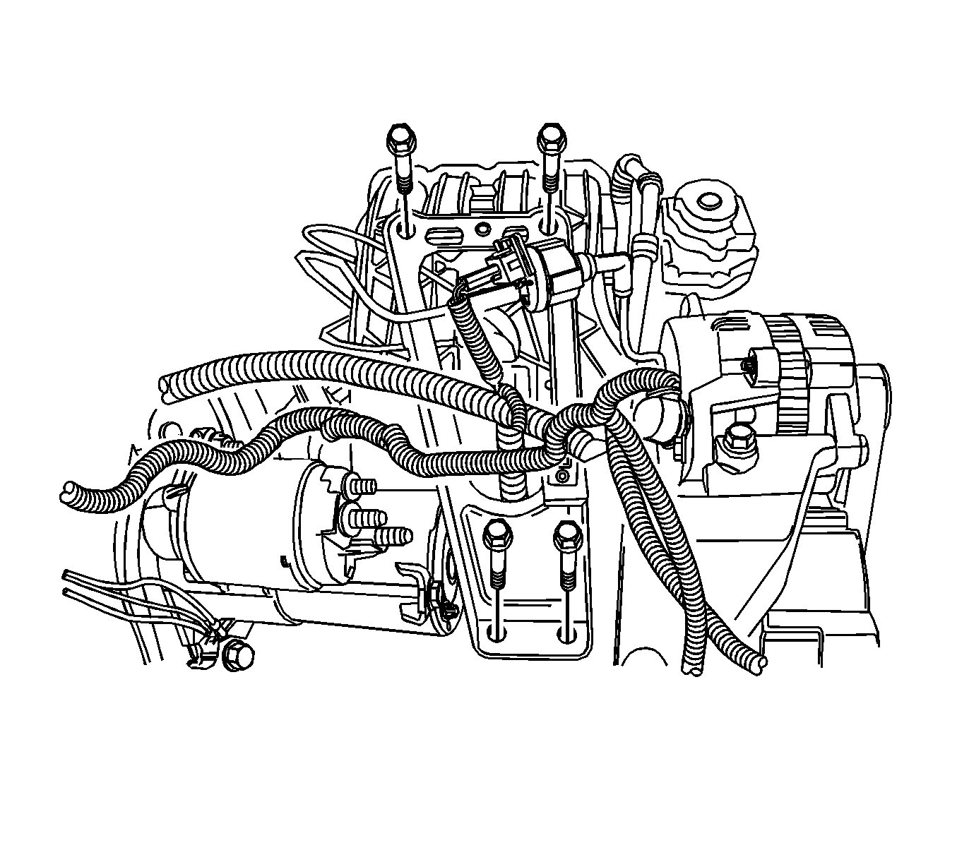
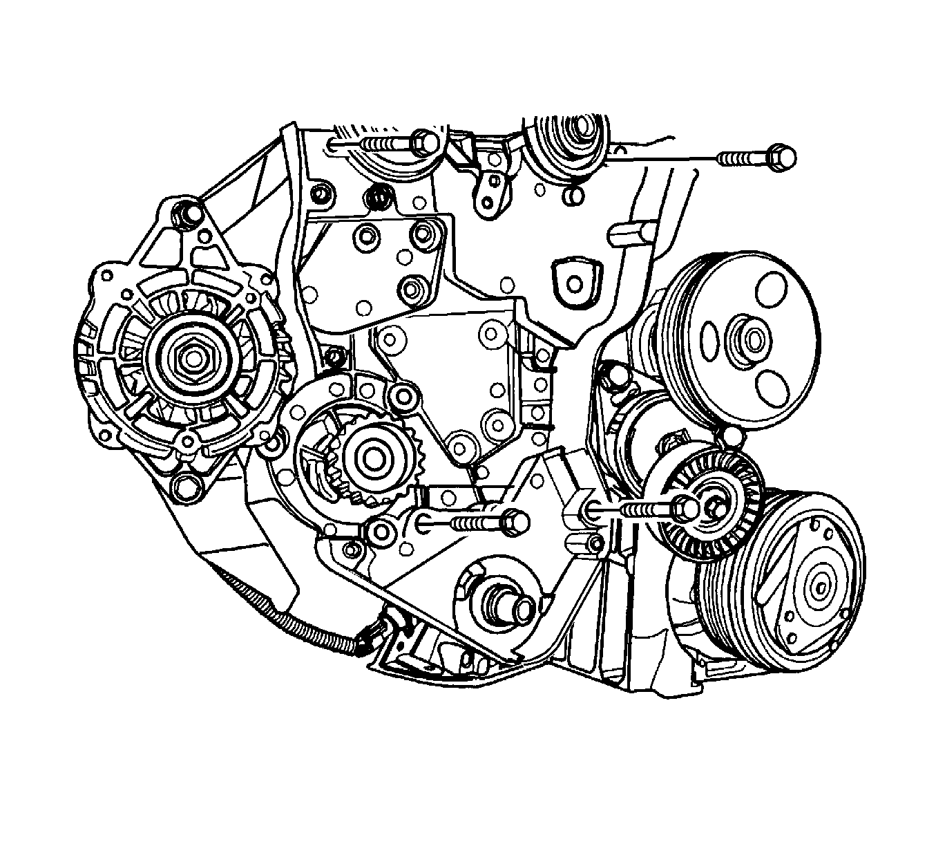
- Install the generator upper retaining bolt.
- Connect the fuel feed line at the fuel rail.
- Connect all the disconnected vacuum hoses and the brake booster vacuum hose at the intake manifold.
- Install the catalytic converter retaining nuts at the exhaust manifold flange.
- Install the rear timing belt cover.
- Install the rear timing belt cover bolts.
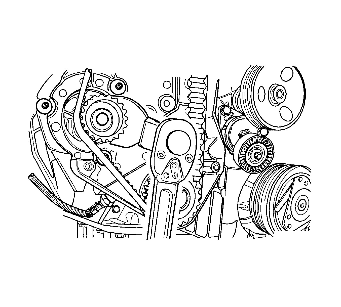
- Install the timing belt automatic tensioner.
- Install the timing belt idler pulley.
- Install the intake and exhaust camshaft gear.
- Apply a small amount of gasket sealant to the corners of the front camshaft caps and the top of the rear camshaft cover-to-cylinder head seal.
- Install the camshaft cover and the gasket. Refer to Valve Rocker Arm Cover Replacement .
- Connect the ignition wires to the spark plugs.
- Install the oil filler cap.
- Connect the engine ventilation hose to the camshaft cover.
- Align the timing marks on the camshaft gears.
- Align the mark on the crank shaft gear with the notch at the bottom of the rear timing belt cover.
- Install the timing belt.
- Rotate the water pump clockwise using the J 42492-A to apply tension to the timing belt.
- Check and adjust the timing belt tension. Refer to Timing Belt Inspection .
- Install the upper and lower front timing belt covers.
- Install the crank shaft pulley bolt.
- Install the serpentine accessory drive belt. Refer to Power Steering Pump Belt Replacement .
- Connect the upper radiator hose to the thermostat housing.
- Install the front wheel and splash shield. Refer to Tire and Wheel Removal and Installation .
- Install the air cleaner housing.
- Connect the breather tube to the cam shaft cover.
- Install the crank shaft pulley bolt.
- Connect the IAT sensor connector.
- Connect the intake manifold pressure sensor, intake air temperature sensor and coolant temperature sensor connector.
- Connect the direct ignition coil connector.
- Connect the fuel injector harness connectors.
- Connect the oxygen sensor connector and the ECM ground terminal at the intake manifold.
- Install the fuel pump fuse.
- Connect the negative battery ground cable.
- Refill the engine cooling system. Refer to Cooling System Draining and Filling .

Notice: Refer to Fastener Notice in the Preface section.
Tighten
Tighten the cylinder head bolts to 25 N·m (18 lb ft) and retighten the cylinder head bolts 70 degrees plus 70 degrees plus 50 degrees.
Tighten
Tighten the intake manifold support bracket upper bolts to the intake manifold to 25 N·m (18 lb ft).
Tighten
Tighten the generator upper retaining bolt to 20 N·m (15 lb ft).
Tighten
Tighten the catalytic converter to exhaust manifold flange nuts to 40 N·m (30 lb ft).
Tighten
Tighten the rear timing belt cover bolts to 10 N·m (89 lb in).
Tighten
Tighten the timing belt automatic tensioner bolts to 25 N·m (18 lb ft).
Tighten
Tighten the timing belt idler pulley bolt to 25 N·m (18 lb ft).
Important: Take extreme care to prevent any scratches, nicks or damage to the camshafts.
Tighten
Tighten the intake and exhaust camshaft gear bolts to 67.5 N·m (49 lb ft).
Tighten
Tighten the water pump retaining bolts to 10 N·m (89 lb in).
Tighten
Tighten the upper and lower front timing belt cover bolts to 10 N·m (89 lb in).
Tighten
Tighten the crank shaft pulley bolt to 95 N·m (70 lb ft) and retighten 30 degrees plus 15 degrees.
Tighten
Tighten the air cleaner housing bolts to 10 N·m (89 lb in).