Tools Required
| • | EN 46359 Puller End Protector |
| • | J 29113 Balancer and Crank Sprocket Installer |
| • | J 37096 Flywheel Holder |
| • | J 41816 Harmonic Balancer Remover |
| • | J 45059 Angle Meter |
Removal Procedure
- Remove the drive belt. Refer to Drive Belt Replacement .
- Raise and support the vehicle. Refer to Lifting and Jacking the Vehicle .
- Remove the right front tire and wheel. Refer to Tire and Wheel Removal and Installation .
- Remove the right engine splash shield. Refer to Engine Splash Shield Replacement .
- Install adjustable jack stands under the frame.
- Loosen the left side frame bolts and remove the right side frame bolts.
- Using the jack stands, lower the right side of the frame in order to access the crankshaft balancer.
- Remove the torque converter covers.
- Install the J 37096 to the flywheel in order to prevent flywheel rotation.
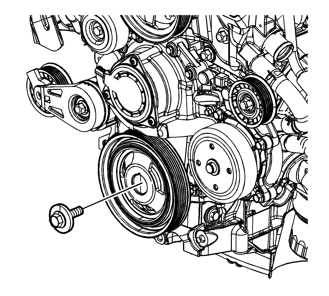
- Remove the crankshaft balancer bolt and the washer.
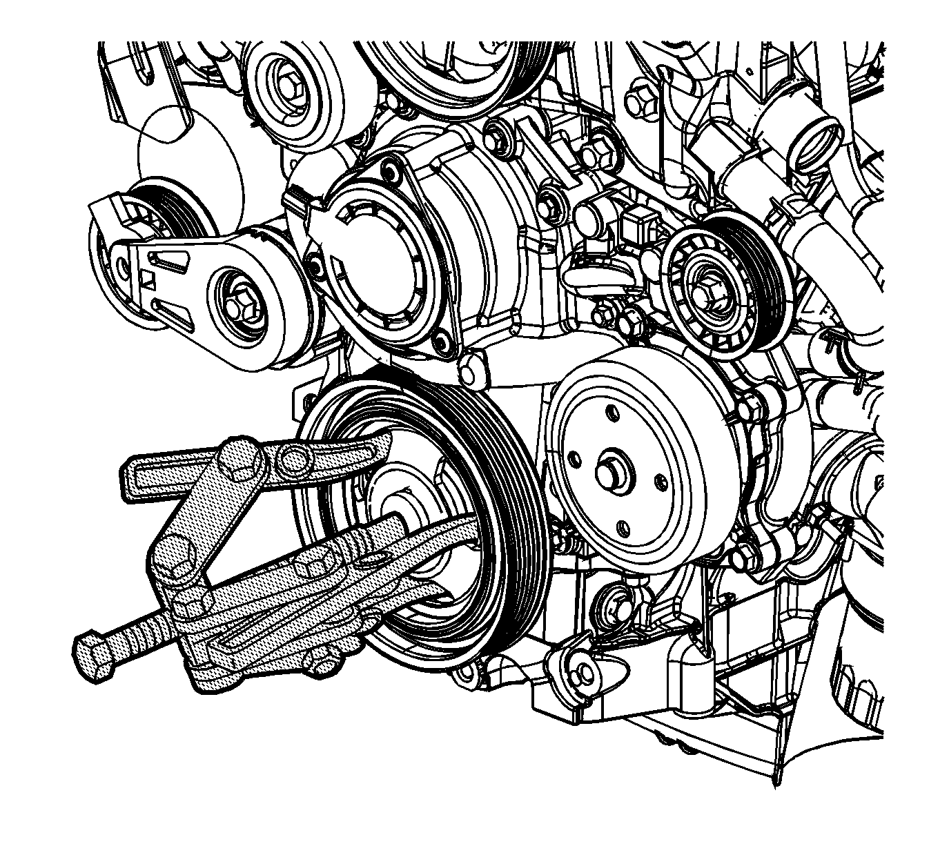
- Remove the crankshaft balancer using the J 41816 and EN 46359 .
Notice: The inertial weight section of the crankshaft balancer is assembled to the hub with a rubber type material. The correct installation procedures (with the proper tool) must be followed or movement of the inertial weight section of the hub will destroy the tuning of the crankshaft balancer.


Notice: Do NOT use a power-assisted tool with the special tool in order to remove or install this component. You cannot properly control the alignment of this component using a power-assisted tool, and this can damage the component.
Installation Procedure
- Apply sealer to the keyway of the crankshaft balancer. Refer to Adhesives, Fluids, Lubricants, and Sealers .
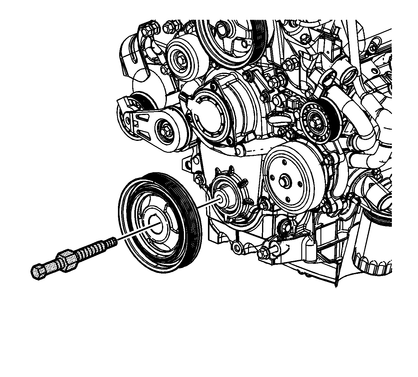
- Place the crankshaft balancer into position over the key in the crankshaft.
- Thread the J 29113 into the crankshaft.
- Rotate the hex nut on the J 29113 in order to install the crankshaft balancer onto the crankshaft.
- Remove the J 29113 from the crankshaft.
- Install the crankshaft balancer washer and the bolt.
- Install the used crankshaft balancer bolt.
- Remove the used crankshaft balancer bolt.
- Install the NEW crankshaft balancer bolt.
- Tighten the crankshaft balancer bolt a first pass to 125 N·m (92 lb ft).
- Tighten the crankshaft balancer bolt a final pass to 130 degrees using the J 45059 .
- Remove the J 37096 from the flywheel.
- Install the torque converter covers.
- Raise the frame into the original position.
- Install and tighten the right and left side frame bolts.
- Install the right engine splash shield. Refer to Engine Splash Shield Replacement .
- Install the right front tire and wheel. Refer to Tire and Wheel Removal and Installation .
- Lower the vehicle.
- Install the drive belt. Refer to Drive Belt Replacement .

Notice: Do NOT use a power-assisted tool with the special tool in order to remove or install this component. You cannot properly control the alignment of this component using a power-assisted tool, and this can damage the component.

Notice: Refer to Fastener Notice in the Preface section.
Tighten
Tighten the used crankshaft balancer bolt to 125 N·m (92 lb ft).
Tighten
Tighten
Tighten the bolts to 100 N·m (74 lb ft) plus an additional 90 degrees using the
J 45059
.
