Steering Wheel Control Switch Assembly Replacement Impala
Removal Procedure
- Disable the SIR system. Refer to Disabling the SIR System in SIR.
- Remove the inflatable restraint steering wheel module. Refer to Inflatable Restraint Steering Wheel Module Replacement in SIR.
- Remove the steering wheel. Refer to Steering Wheel Replacement .
- Remove the steering wheel controls wire harness from the retainers in the steering wheel aluminum insert and plastic back shroud.
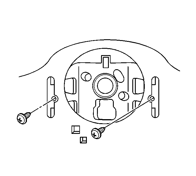
- Remove the plastic back shroud screws and the plastic back shroud on the back of the steering wheel.
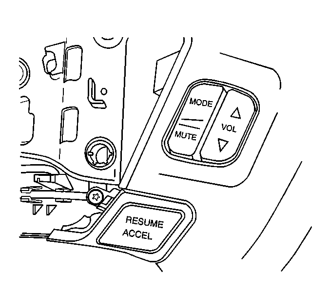
- Carefully push on the back of the steering wheel radio control switch through the access opening in the back of the steering wheel switch pocket.
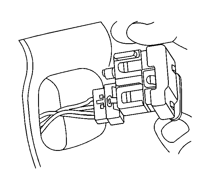
- Disconnect the electrical connector from the back of the steering wheel radio control switch.
- Remove the steering wheel radio control switch.
Installation Procedure
- Position the steering wheel radio control switch to the steering wheel. Route the radio control wire harness through the access opening in the back of the steering wheel switch pocket.
- Connect the electrical connector to the back of the steering wheel radio control switch.
- Carefully install the steering wheel controls switch into the steering wheel switch pocket.
- Install the plastic back shroud to the back of the steering wheel with the plastic back shroud screws.
- Install the steering wheel radio controls wiring harness to the retainers in the steering wheel insert and back shroud. Make sure the wiring is not routed underneath any of the four SIR module mounting holes in the steering wheel.
- Install the plastic back shroud screws and the plastic back shroud on the back of the steering wheel.
- Install the steering wheel. Refer to Steering Wheel Replacement .
- Install the inflatable restraint steering wheel module. Refer to Inflatable Restraint Steering Wheel Module Replacement in SIR.
- Enable the SIR system. Refer to Enabling the SIR System in SIR.

Important: The steering wheel switch wiring harness must be kept below the white insulators on the back of the steering wheel when installing the plastic back shroud. Do not pinch the wire harness between the steering wheel urethane and the plastic back shroud.

Notice: Use the correct fastener in the correct location. Replacement fasteners must be the correct part number for that application. Fasteners requiring replacement or fasteners requiring the use of thread locking compound or sealant are identified in the service procedure. Do not use paints, lubricants, or corrosion inhibitors on fasteners or fastener joint surfaces unless specified. These coatings affect fastener torque and joint clamping force and may damage the fastener. Use the correct tightening sequence and specifications when installing fasteners in order to avoid damage to parts and systems.
Tighten
Tighten the plastic back shroud screws to 2 N·m (18 lb in).
Steering Wheel Control Switch Assembly Replacement Monte Carlo
Removal Procedure
- Disable the SIR system. Refer to Disabling the SIR System in SIR.
- Remove the inflatable restraint steering wheel module. Refer to Inflatable Restraint Steering Wheel Module Replacement in SIR.
- Remove the steering wheel. Refer to Steering Wheel Replacement .
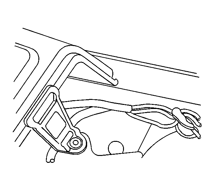
- Remove the steering wheel controls wire harness from the retainers in the steering wheel aluminum insert and plastic back shroud.
- Remove the switch bezel screw at the steering wheel insert.
- Pull upward in order to remove the switch bezel from the steering wheel.
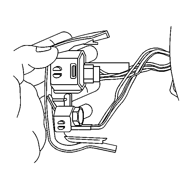
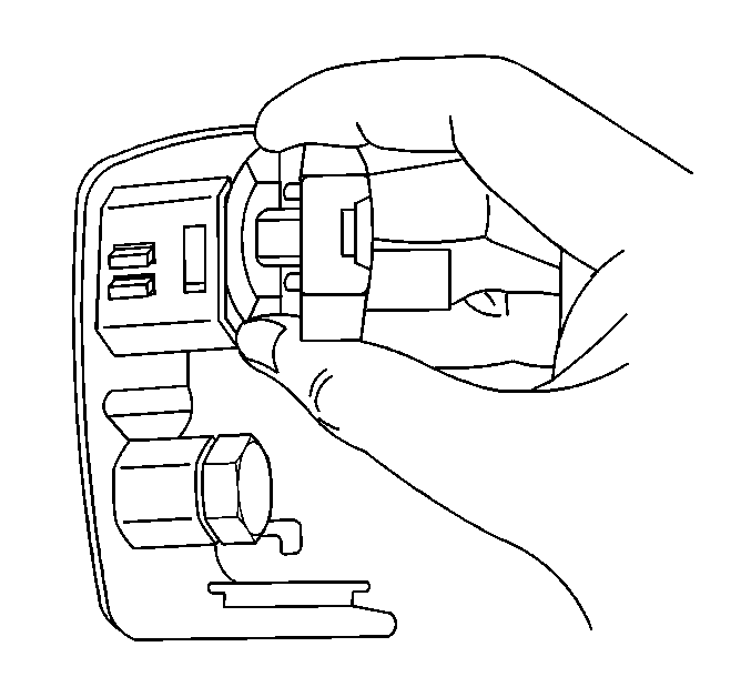
- Disconnect the electrical connectors from the back of the switches.
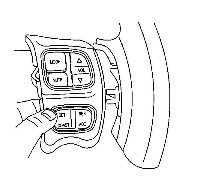
- Remove the switch assembly (switches and bezel).
Installation Procedure
- Position the steering wheel switch to the steering wheel.
- Connect the electrical connectors to the back of the switches.
- Install the switch bezel to the retainers in the steering wheel urethane.
- Route the switch wire harness behind the switch bezel leg and over the top of the aluminum steering wheel side spoke.
- Install the switch bezel screw to the to the steering wheel insert.
- Install the steering wheel controls wire harness to the retainers in the steering wheel insert and back shroud. Make sure the wire is not routed underneath any of the three SIR mounting holes in the steering wheel.
- Install the inflatable restraint steering wheel module. Refer to Inflatable Restraint Steering Wheel Module Replacement in SIR.
- Enable the SIR system. Refer to Enabling the SIR System in SIR.


This positions the switch bezel leg over the screw opening in the steering wheel insert.

Important: Do not pinch the wire harness when installing the cruise bezel screw.
