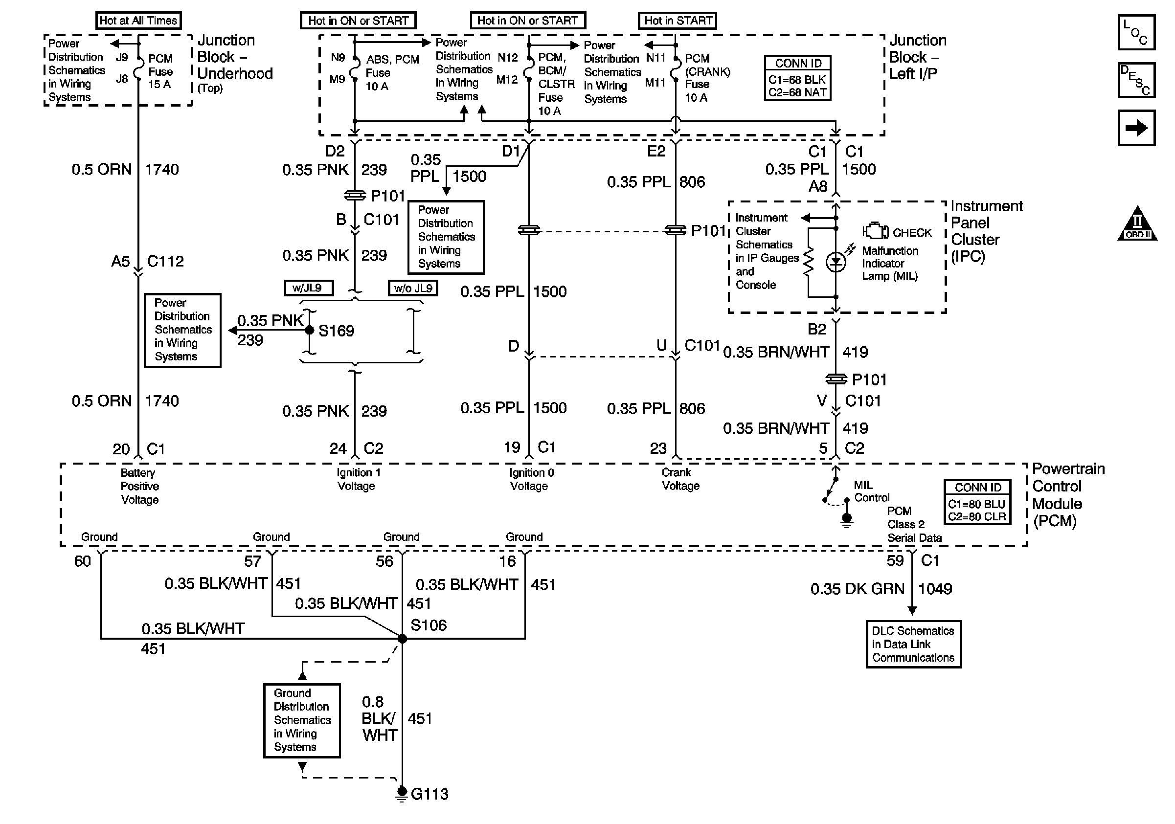
| Figure 1: |
Data Link, Grounds, MIL, and Power
|
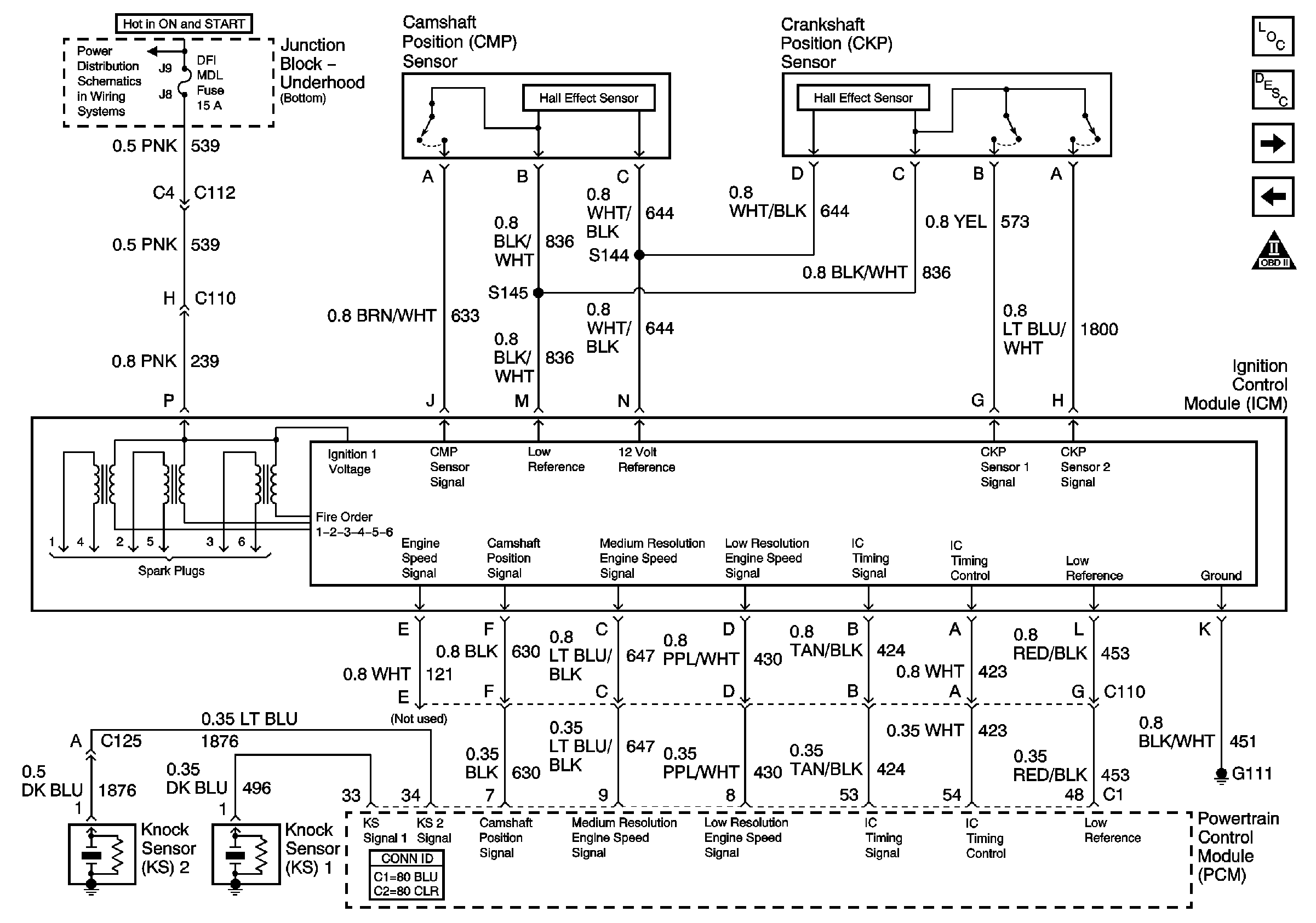
| Figure 2: |
Ignition Control
|
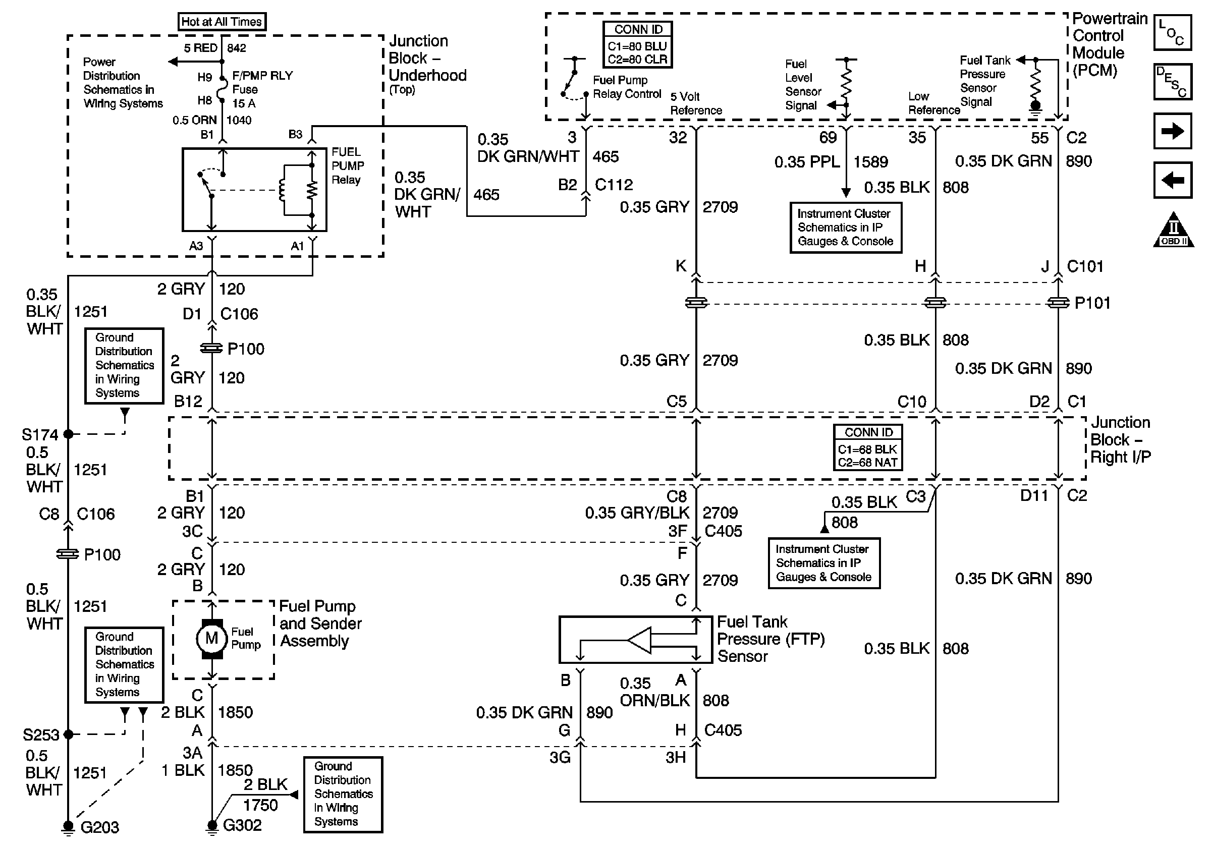
| Figure 3: |
Fuel Controls
|
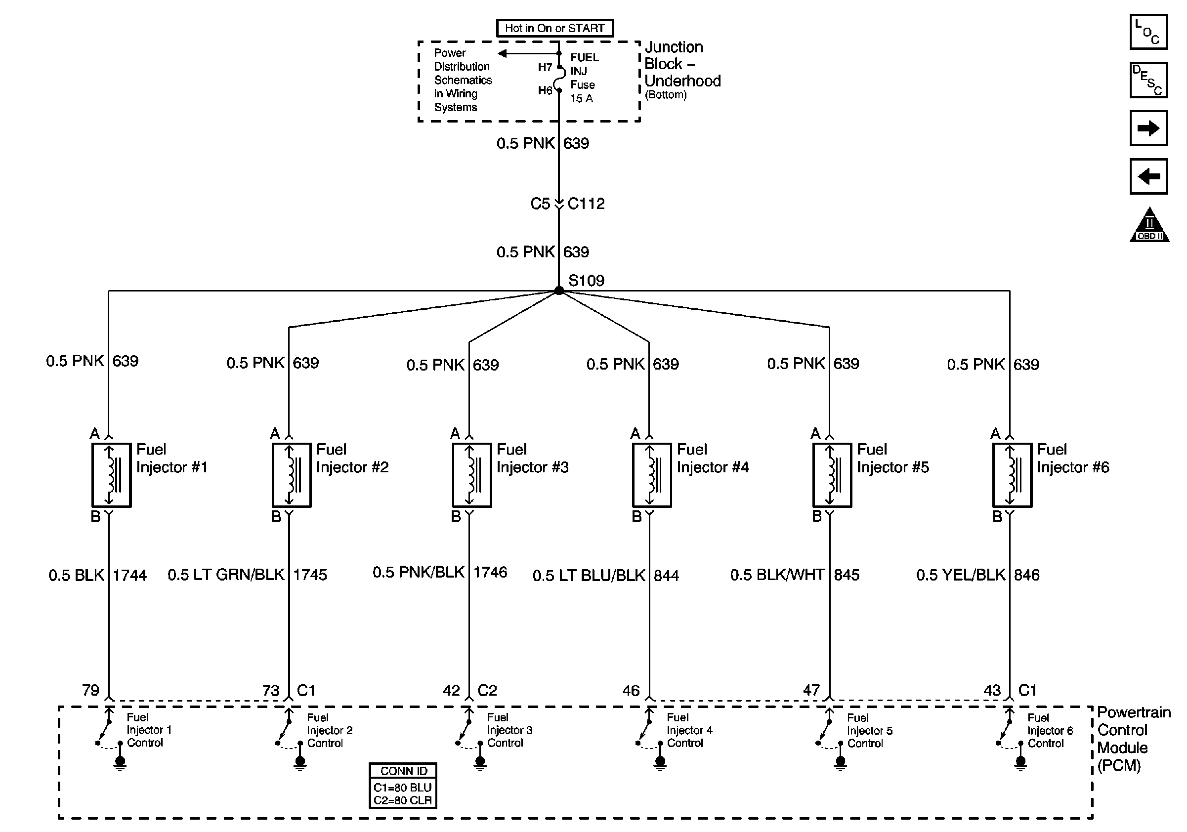
| Figure 4: |
Fuel Injectors
|
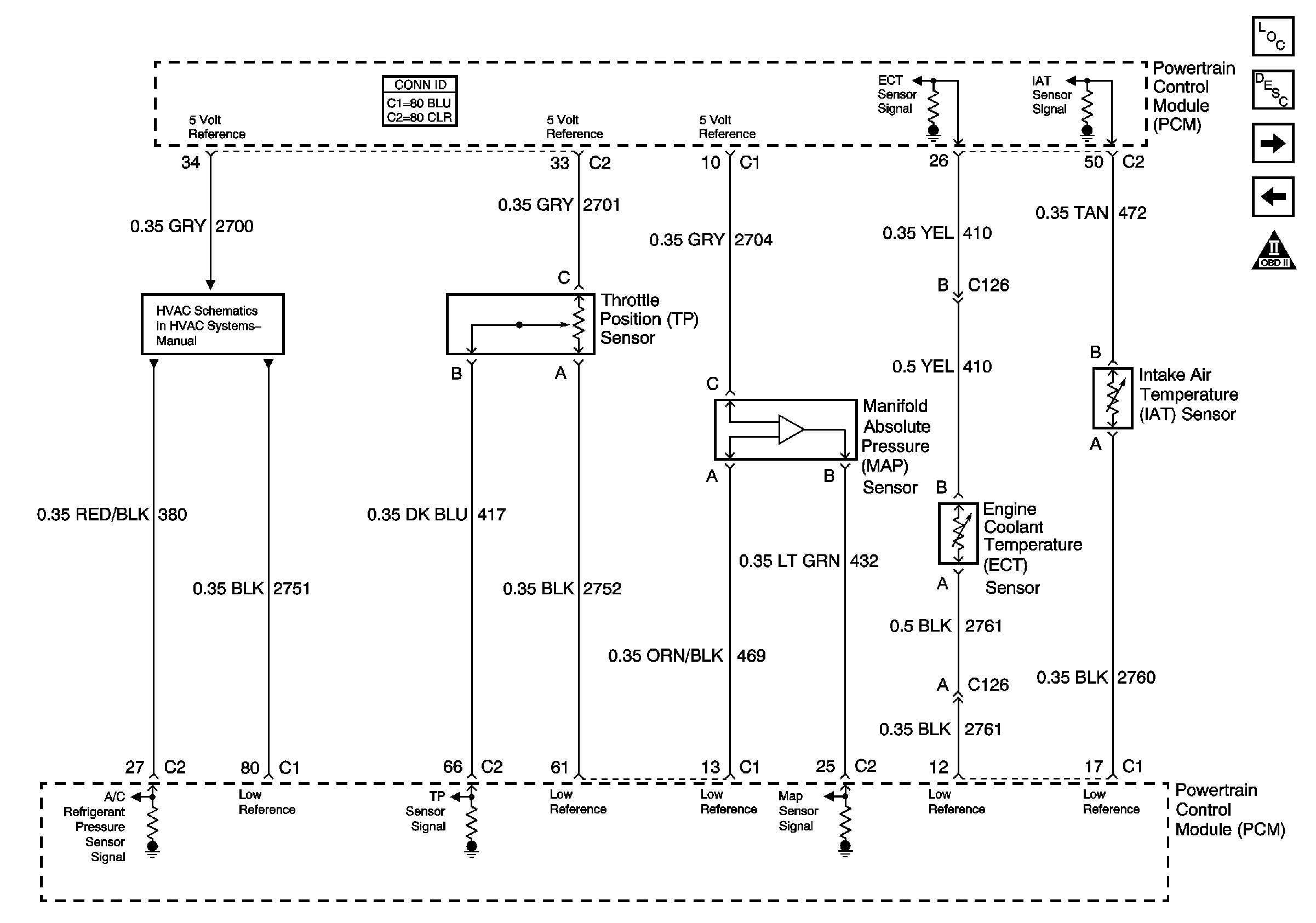
| Figure 5: |
ECT, IAT, MAP, and TP Sensors, References to HVAC
|
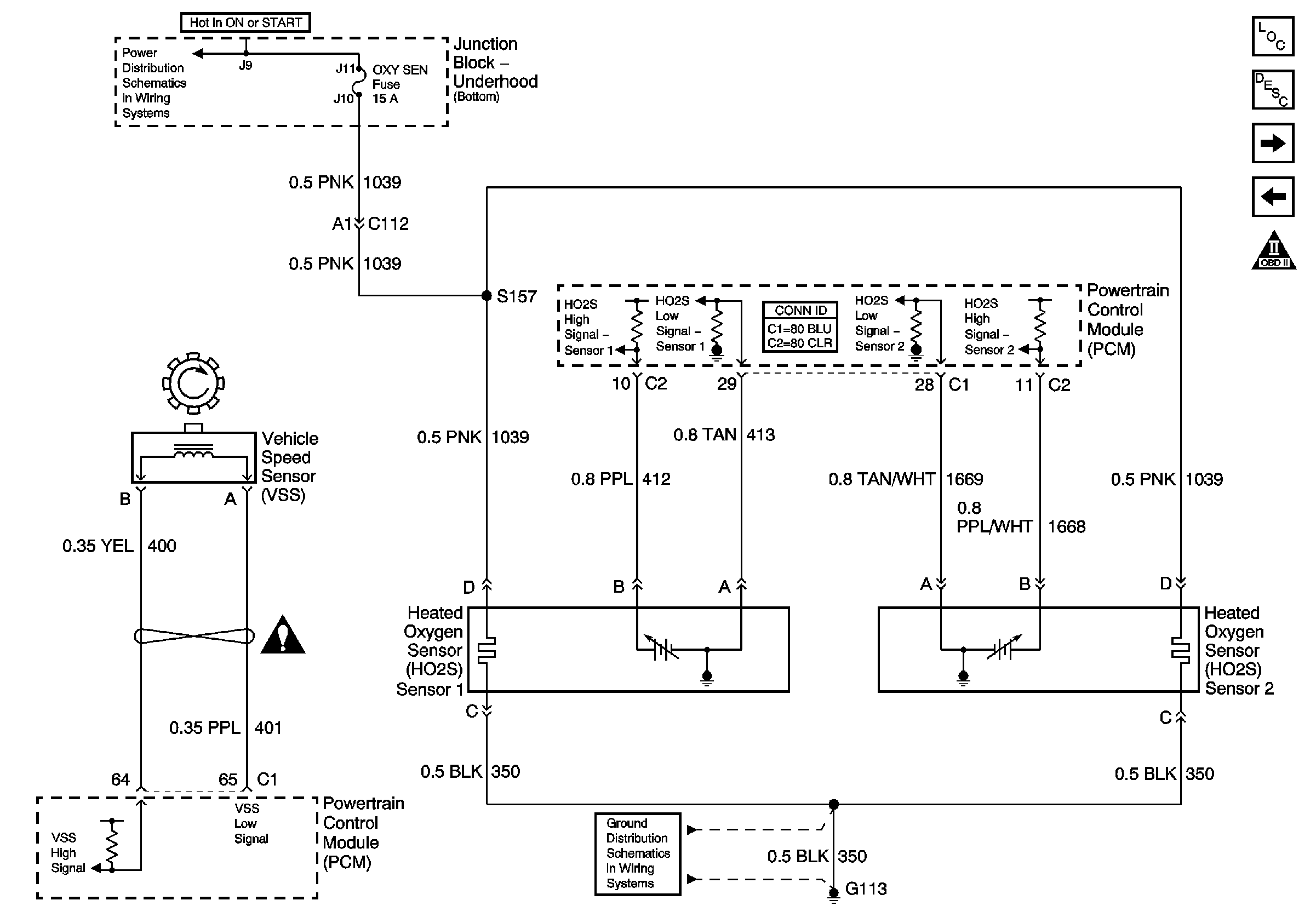
| Figure 6: |
HO2S and VSS
|
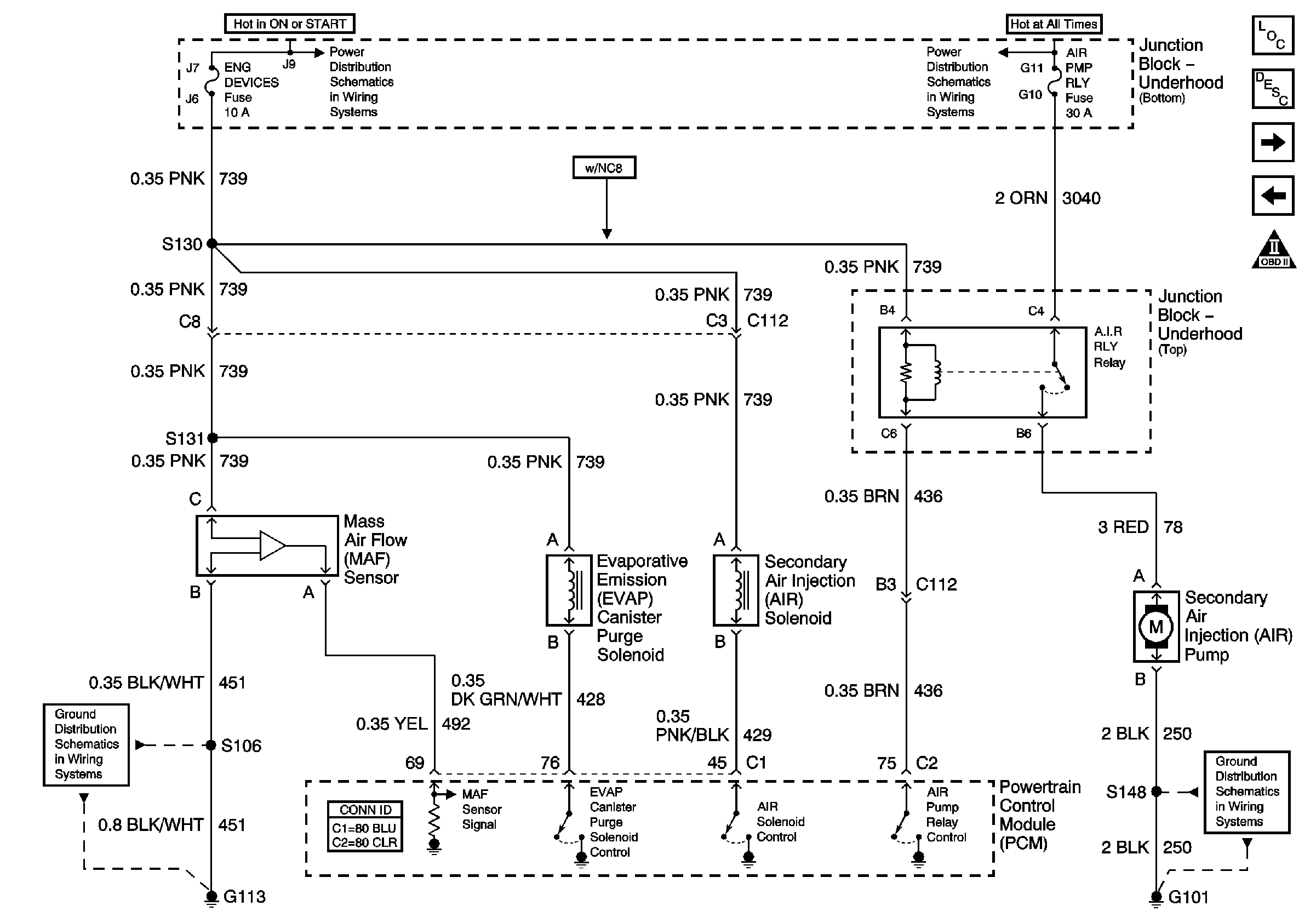
| Figure 7: |
Air Injection, EVAP Purge, and MAF
|
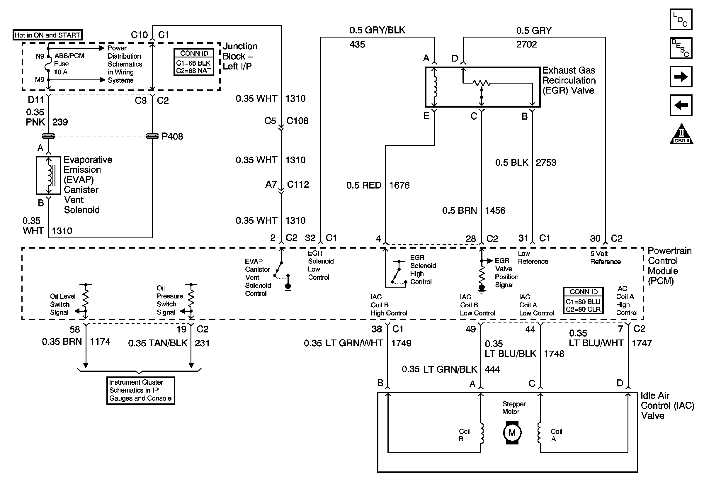
| Figure 8: |
EGR, EOP, IAC, and EVAP Vent
|
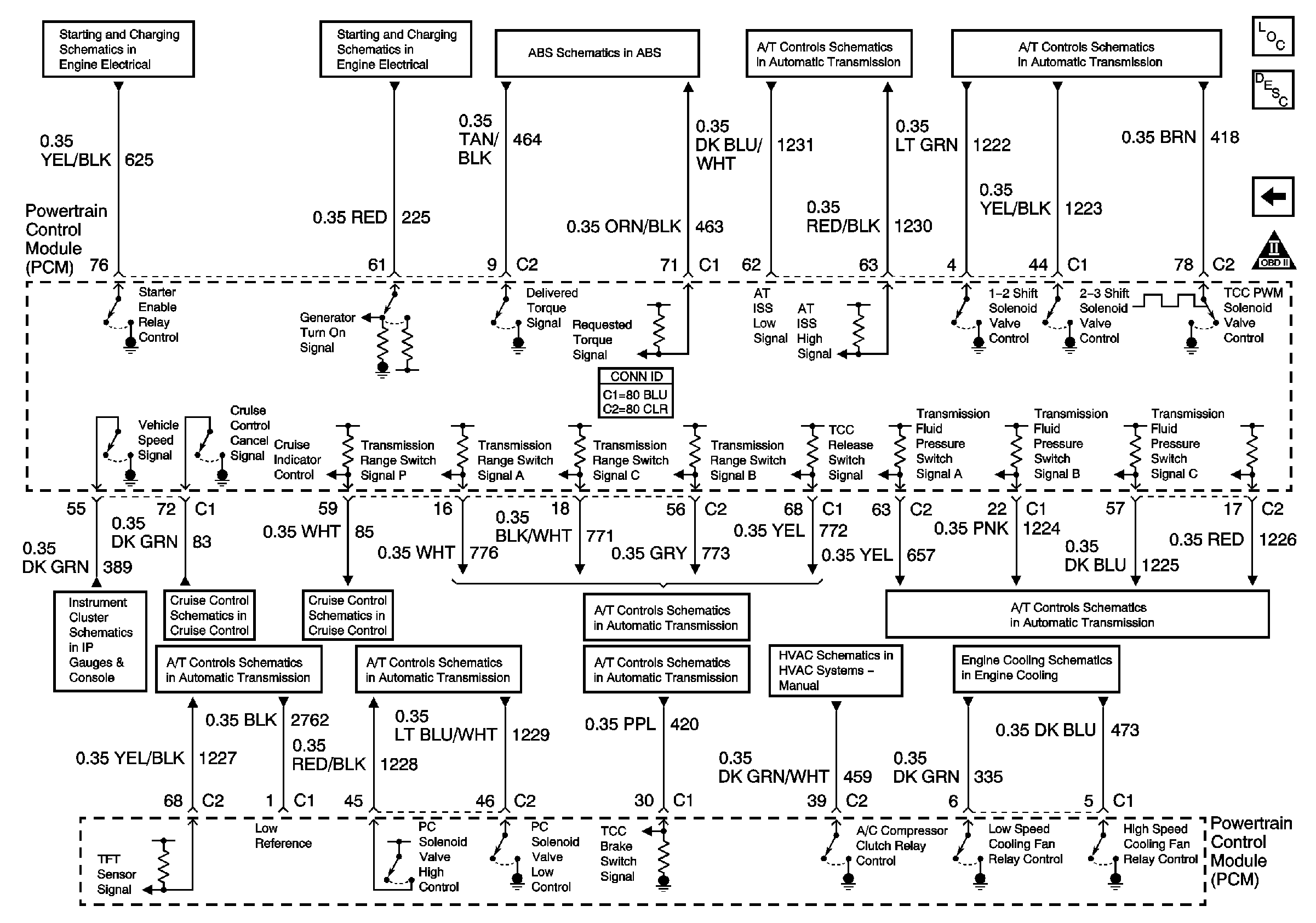
| Figure 9: |
PCM References
|
