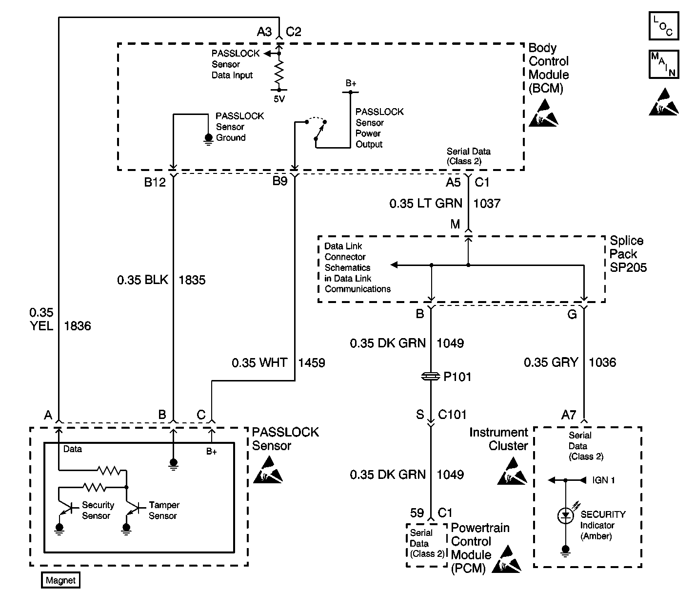
Circuit Description
The Passlock theft deterrent system contains a Passlock sensor that is part of the ignition lock cylinder assembly. The body control module (BCM) provides voltage (B+) to the Passlock sensor through the Passlock sensor power circuit when the ignition switch is in the ACCESSORY, ON, or START position. The BCM also provides a 5-volt reference to the Passlock data circuit. The BCM provides ground to the Passlock sensor through the Passlock sensor ground circuit. The Passlock sensor interfaces with the BCM through the Passlock sensor data circuit.
When you turn the ignition switch to the START position with the proper key, the Passlock sensor applies a unique resistance value to the Passlock Data Circuit. The Passlock Data Circuit pulls the 5-volt reference down to a unique voltage value, which is measured by the BCM. This voltage signal is unique and varies from vehicle to vehicle. When you attempt to start the engine, the BCM compares a previously stored (learned) voltage value with the circuit voltage value:
| • | When the values match, the BCM sends a fuel enable password via the Class 2 serial data link to the powertrain control module (PCM). Then the PCM enables the crank relay, and allows fuel delivery to the engine. |
| • | When the values do not match, the BCM sends a fuel disable password via the Class 2 serial data link to the powertrain control module (PCM). As a result, the PCM disables the crank relay, and does not allow fuel delivery to the engine. |
Conditions for Setting the DTC
The BCM detects a short to B+ on the Passlock sensor power circuit for 1 second, with the ignition switch in the OFF position and the BCM in the wake-up state. Refer to Body Control System Operation in Body Control System for additional information regarding the BCM wake-up/sleep state.
Action Taken When the DTC Sets
| • | The BCM stores DTC B2948 in memory. |
| • | The BCM does not send a message to the instrument cluster in order to turn the SECURITY indicator ON. The security indicator will stay off. |
Conditions for Clearing the DTC
| • | DTC B2948 clears when the BCM no longer detects a short to B+ on the Passlock sensor power circuit with the ignition switch OFF and the BCM is in the wake-up state. |
| • | When a short to B+ is present in the Passlock sensor power circuit, turning the ignition switch from OFF to Accessory will clear the DTC as a current DTC. This DTC will reset as a current DTC when the ignition switch is OFF and the BCM is in the wake-up state. |
Diagnostic Aids
Inspect for a short to B+ in the Passlock sensor power circuit with the ignition switch OFF. The BCM inspects for this DTC when the ignition switch is in the OFF position only.
If this DTC is a history DTC the problem may be intermittent. Refer to Circuit Testing and Testing for Intermittent Conditions and Poor Connections in Wiring Systems.
When BCM diagnostics and repairs are completed, refer to Powertrain On Board Diagnostic (OBD) System Check in Engine Controls - 3.4L or Powertrain On Board Diagnostic (OBD) System Check in Engine Controls - 3.8L for additional information on PCM related DTCs that may be set during the diagnostic process.
Test Description
The numbers below refer to the step numbers on the diagnostic table.
-
Always perform the Theft Deterrent Diagnostic System Check before attempting to diagnose this DTC.
-
This step tests for a short to B+ in the Passlock sensor power circuit.
-
This step tests for a faulty PASSLOCK sensor.
-
This step tests for a faulty BCM.
Step | Action | Value(s) | Yes | No |
|---|---|---|---|---|
Was the Theft Deterrent Diagnostic System Check performed? | -- | Go to Step 2 | ||
2 |
Is the DTC a history DTC? | -- | Go to Testing for Intermittent Conditions and Poor Connections | Go to Step 3 |
Is the voltage measured less than the specified value? | 2V | Go to Step 4 | Go to Step 6 | |
Is the voltage measured less than the specified value? | 2V | Go to Step 5 | Go to Step 7 | |
Does BCM DTC B2948 reset as a current DTC? | -- | Go to Step 8 | Go to Step 9 | |
6 | Repair short to B+ in the Passlock sensor power circuit. Refer to Circuit Testing and Testing for Intermittent Conditions and Poor Connections in Wiring Systems. Is the repair complete? | -- | Go to Step 10 | -- |
7 |
Is the repair complete? | -- | Go to Step 10 | -- |
8 |
Is the repair complete? | -- | Go to Step 10 | -- |
9 | The malfunction is intermittent or not present at this time. Refer to Diagnostic Aids for more information. Is the action complete? | -- | Go to Step 10 | -- |
10 |
Are any current BCM DTCs present? | -- | System OK |
