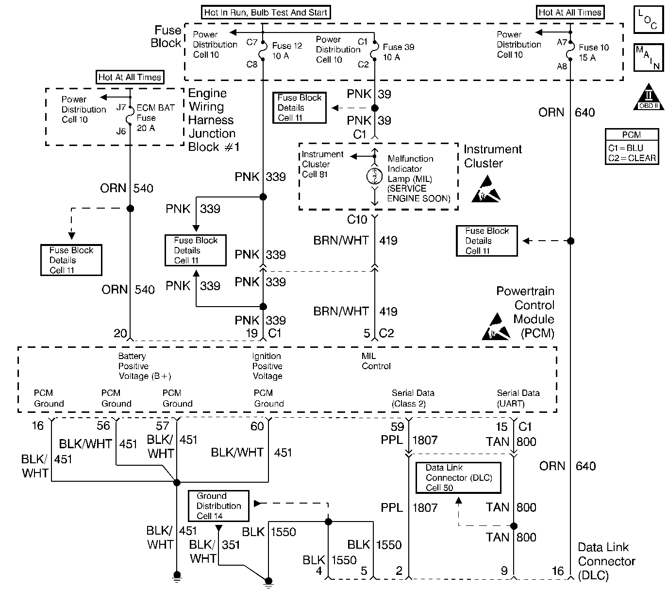
Circuit Description
The Powertrain On Board Diagnostic (OBD) System Check must be the starting point for any driveability complaint diagnosis. Before using this procedure, you should perform a careful visual/physical check of the PCM and engine grounds for being clean and tight. The Powertrain On Board Diagnostic (OBD) System Check is an organized approach to identifying a problem created by an electronic engine control system malfunction. No MIL with the key ON, engine not running and DTC P0650 set suggests an open in the MIL driver circuit.
Diagnostic Aids
An intermittent may be caused by a poor connection, rubbed through wire insulation or a wire broken inside the insulation. Check for the following items:
| • | Inspect the PCM harness and connectors for improper mating, broken locks, improperly formed or damaged terminals, poor terminal to wire connection, and damaged harness. Refer to Intermittents and Poor Connections Diagnosis Repairing Connector Terminals and Connector Repairs . |
| • | If the engine runs OK, check for a faulty light bulb, an open in the MIL driver circuit, or an open in the instrument cluster ignition feed. Refer to Wiring Repairs |
| • | If the engine cranks but will not run, check for an open PCM ignition or battery feed or a poor PCM to engine ground. |
Test Description
The numbers below refer to the step numbers on the Diagnostic Table:
-
A no MIL condition accompanied by a no start condition suggests a faulty PCM ignition feed or battery feed circuit.
-
Using a test light connected to battery positive voltage, probe each of the PCM ground terminals to ensure that a good ground is present.
-
This vehicle is equipped with a PCM which utilizes an Electrically Erasable Programmable Read Only Memory (EEPROM). When the PCM is being replaced, the new PCM must be programmed. Refer to Powertrain Control Module Replacement/Programming .
Step | Action | Value(s) | Yes | No |
|---|---|---|---|---|
1 | Was the Powertrain On Board Diagnostic (OBD) System Check performed? | -- | ||
Attempt to start the engine. Does the engine start? | -- | |||
3 | Check the fuse for the instrument cluster ignition feed circuit. Is the fuse OK? | -- | ||
4 |
Is the test light ON? | -- | ||
5 |
Is the MIL ON? | -- | ||
6 | Check the PCM ignition feed and battery feed fuses. Are both of the fuses OK? | -- | ||
7 |
Is the test light ON? | -- | ||
8 | Probe the battery feed circuit at the PCM harness connector with a test light to ground. Is the test light ON? | -- | ||
Was a problem found? | -- | |||
10 |
Was a problem found? | -- | ||
11 |
Was a problem found? | -- | ||
12 | Repair open in the ignition feed circuit to the instrument cluster. Refer to Power and Grounding Components in Wiring Systems. Did you complete the repair? | -- | -- | |
13 | Locate and repair open in PCM battery feed circuit or PCM ignition feed circuit as necessary. Refer to Power and Grounding Components in Wiring Systems. Did you complete the repair? | -- | -- | |
14 | Locate and repair short to ground in PCM ignition feed circuit or PCM battery feed circuit as necessary. Refer to Power and Grounding Components in Wiring Systems. Did you complete the repair? | -- | -- | |
15 | Locate and repair short to ground in the instrument cluster ignition feed circuit. Refer to Power and Grounding Components in Wiring Systems. Did you complete the repair? | -- | -- | |
Replace the PCM. Important: : Replacement PCM must be programmed. Refer to Powertrain Control Module Replacement/Programming . Did you complete the repair? | -- | -- | ||
17 |
Was a problem found? | -- | Go to Instrument Panel in Electrical Diagnosis . |
