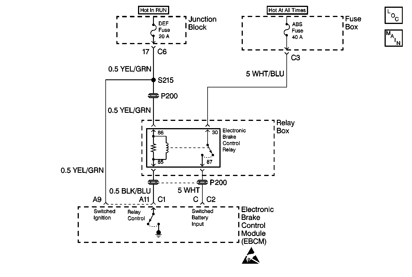
Circuit Description
Ignition voltage is supplied to terminal 86 of the Electronic Brake Control Relay. The above condition enables the EBCM to energize the pullin coil by completing the ground circuit at connector terminal A11 of the EBCM. The magnetic field that is created closes the contacts of the Electronic Brake Control Relay . The magnetic field also allows the battery voltage and the current through the Electronic Brake Control Relay terminal 30 to be supplied to the EBCM through connector terminal C. Connector terminal C supplies power to the EBCM, which supplies power to the motors.
Conditions for Setting the DTC
DTC 1216 can set at any time after the Electronic Brake Control Relay is commanded ON. This test detects an open in the coil circuit of the Electronic Brake Control Relay. An open in this circuit will not allow the Electronic Brake Control Relay to be energized therefore preventing power to the motors and to the solenoids.
A DTC C1286 will be set with DTC C1216 if the rear channel is not expected to be in the home position.
Important: DTC C1214 will also set with this DTC. Follow the diagnostic table for this DTC first, if DTC C1214 is set as current DTC.
| • | A malfunction DTC is stored. |
| • | The ABS is disabled. |
| • | The ABS warning indicators turn ON. |
Conditions for Clearing the DTC
| • | The condition responsible for setting the DTC no longer exists, and the Scan Tool Clear DTCs function is used. |
| • | 100 drive cycles pass, and DTCs are not detected. A drive cycle consists of the following actions: |
| • | Starting the vehicle |
| • | Driving the vehicle over 16 km/h (10 mph) |
| • | Stopping the vehicle |
| • | Turning the ignition OFF |
Diagnostic Aids
The following conditions may cause an intermittent malfunction:
| • | A poor connection |
| • | Rubbed-through wire insulation |
| • | A broken wire inside the insulation |
Use the enhanced diagnostic function of the Scan Tool in order to measure the frequency of the malfunction.
If the frequency of the malfunction is high, but is currently intermittent, inspect for high coil resistance. Use a J 39200 in order to measure for high coil resistance by measuring between Electronic Brake Control Relay terminal 85 and terminal 86. If the resistance shows greater than 95 ohms, replace the Electronic Brake Control Relay.
Thoroughly inspect any circuitry that may be causing the intermittent complaint for the following conditions:
| • | Backed out terminals |
| • | Incorrect mating |
| • | Incorrectly formed terminals or damaged terminals |
| • | Poor terminal-to-wiring connections |
| • | Physical damage to the wiring harness |
After completing the diagnosis, clear the DTCs . Test drive the vehicle for three drive cycles in order to verify that the DTC does not reset. Use the following procedure in order to complete one drive cycle:
- Start the vehicle.
- Drive the vehicle over 16 km/h (10 mph).
- Stop the vehicle.
- Turn the ignition to the OFF position.
Test Description
-
This test determines if the EBCM is capable of controlling the electronic brake control relay as commanded.
-
This test determines if battery voltage is being supplied to the DEF fuse.
-
This test determines if battery voltage is being supplied to the Electronic Brake Control Relay.
-
This test ensures that there is continuity through the pull-in coil of the electronic brake control relay.
-
This test checks for an open or high resistance in the electronic brake control relay control circuit between the electronic brake control relay and the EBCM.
-
This test determines if the malfunction is due to the EBCM.
Step | Action | Value(s) | Yes | No | ||||||||||
|---|---|---|---|---|---|---|---|---|---|---|---|---|---|---|
|
Important: Zero the J 39200 test leads before making any resistance measurements. Refer to the J 39200 user's manual. | ||||||||||||||
1 | Was A Diagnostic System Check-ABS performed? | -- | ||||||||||||
Do not start the engine. Does the Scan Tool indicate that the Electronic Brake Control Relay is ON, and is the voltage within the specified range? | Battery Voltage | |||||||||||||
3 | Remove and inspect the DEF fuse. Is the fuse open? | -- | ||||||||||||
Is the voltage within the specified range? | Battery Voltage | Go to Power Distribution Schematics in Wiring Systems | ||||||||||||
Is the voltage within the specified range? | Battery Voltage | |||||||||||||
Use the J 39200 in order to measure the resistance between the Electronic Brake Control Relay terminals 85 and 86. Is the resistance within the specified range? | 65-95 ohms | |||||||||||||
Is the resistance within the specified range? | 0-2 ohms | |||||||||||||
8 |
Are there signs of damage, poor terminal contact or corrosion? | -- | ||||||||||||
Do not start the engine. Does DTC C1216 set as a current DTC? | -- | |||||||||||||
10 | Inspect the YEL/GRN wire between the Junction Block and the Relay Box for damage that may cause a short to ground. Is there any damage present? | -- | ||||||||||||
11 |
Is the repair complete? | -- | -- | |||||||||||
12 | Replace the DEF fuse. Is the repair complete? | -- | -- | |||||||||||
13 | Repair the open or high resistance in the YEL/GRN wire between the Junction Block and the Relay Box. Refer to Wiring Repairs in Wiring Systems. Is the repair complete? | -- | -- | |||||||||||
14 | Replace the Electronic Brake Control Relay. Refer to Electronic Brake Control Relay Replacement . Is the repair complete? | -- | -- | |||||||||||
15 | Repair the open or high resistance in the BLK/BLU wire between the relay box and the EBCM. Refer to Wiring Repairs in Wiring Systems. Is the repair complete? | -- | -- | |||||||||||
16 | Replace all of the terminals or connectors that display signs of poor terminal contact, corrosion, or damaged terminal(s). Refer to Connector Repairs in Wiring Systems. Is the repair complete? | -- | -- | |||||||||||
17 | Replace the EBCM. Refer to Electronic Brake Control Module Replacement . Is the repair complete? | -- | -- | |||||||||||
18 | The malfunction is intermittent or is not present at this time. Refer to Diagnostic Aids for more information. Is the action complete? | -- | System OK | -- | ||||||||||
