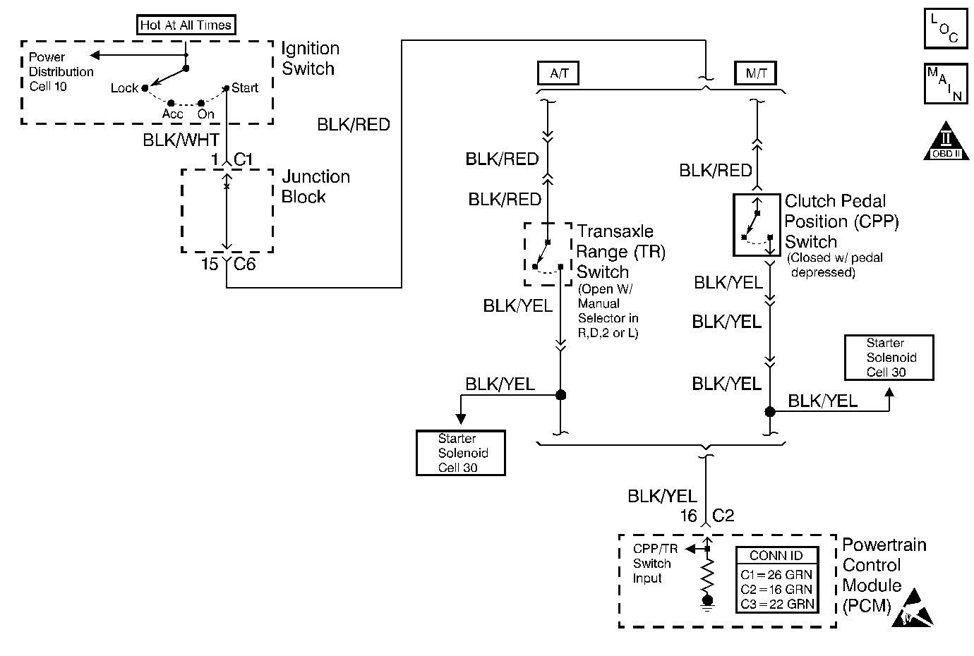
Circuit Description
The powertrain control module (PCM) receives a engine start signal input (battery voltage) from the ignition switch when the engine is being cranked. The engine start signal input passes through the clutch pedal position (CPP) switch. The PCM increases the volume of fuel injected for improved starting when the engine start signal is present. The engine will start without the PCM receiving the engine start signal.
Conditions for Setting the DTC
| • | No engine start signal to the PCM when the starter is engaged. |
| • | Low voltage at the PCM while cranking the engine. |
| • | High voltage at the PCM after starting the engine. |
| • | Condition occurs once per drive cycle for 0.4 seconds. |
Action Taken When the DTC Sets
| • | The Malfunction Indicator Lamp (MIL) will illuminate after two consecutive ignition cycles in which the diagnostic runs with the fault active. |
| • | The PCM will record operating conditions at the time the diagnostic fails. This information will be stored in the Freeze Frame buffer. |
Conditions for Clearing the MIL/DTC
| • | The MIL turns OFF after three consecutively passing trips without a fault present. |
| • | A History DTC clears after 40 consecutive warm-up cycles without a fault. |
| • | Use the scan tool Clear DTC Information function or disconnect the PCM battery feed in order to clear the DTC. |
Diagnostic Aids
An intermittent malfunction may be caused by a problem in the CPP switch electrical circuit. Inspect the wiring harness and components for any of the following conditions:
| • | Backed out terminals |
| • | Improper mating of terminals |
| • | Broken electrical connector locks |
| • | Improperly formed or damaged terminals |
| • | Faulty terminal to wire connections |
| • | Physical damage to the wiring harness |
| • | A broken wire inside the insulation |
| • | Corrosion of electrical connections, splices, or terminals |
If a DTC P1500 cannot be duplicated, the information included in the Freeze Frame data can be useful in determining vehicle operating conditions when the DTC was first set.
Test Description
The numbers below refer to the step numbers in the Diagnostic Table.
-
The Powertrain OBD System Check prompts the technician to complete some basic checks and store the freeze frame data on the scan tool if applicable. This creates an electronic copy of the data taken when the fault occurred. The information is then stored in the scan tool for later reference.
-
This step determines that the fault is present.
-
The PCM receives 8 to 12 volts on the engine start signal circuit while the engine is cranking. An engine that is running should have 0.0 volts on the engine start signal circuit.
-
The PCM shows no voltage on the engine start signal circuit when the engine is running unless there is a short to voltage.
Step | Action | Value(s) | Yes | No |
|---|---|---|---|---|
Did you perform the Powertrain On-Board Diagnostic (OBD) System Check? | -- | |||
Is a DTC P1500 set? | -- | Go to Diagnostic Aids | ||
Is the voltage near the specified value while cranking the engine? | 8 to 12 volts | |||
4 |
Is the action complete? | -- | -- | |
Measure the voltage at the PCM electrical connector engine start signal circuit with the engine running. Is the voltage at the specified value? | 0 volts | |||
6 |
Is the action complete? | -- | -- | |
7 |
Was repair necessary? | -- | ||
8 | Replace the PCM. Refer to Powertrain Control Module Replacement . Is the action complete? | -- | -- | |
9 |
Are any DTCs displayed on the scan tool? | -- | Go to the Applicable DTC Table | System OK |
