Starter Replacement LE5
Removal Procedure
- Disconnect the negative battery cable. Refer to Battery Negative Cable Disconnection and Connection.
- Raise and support the vehicle. Refer to Lifting and Jacking the Vehicle.
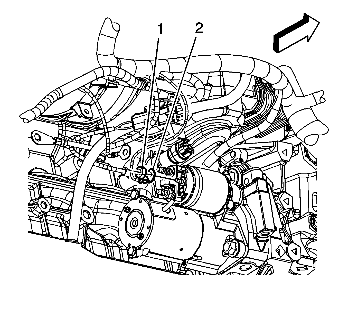
- Remove the "S" terminal connector from the starter solenoid.
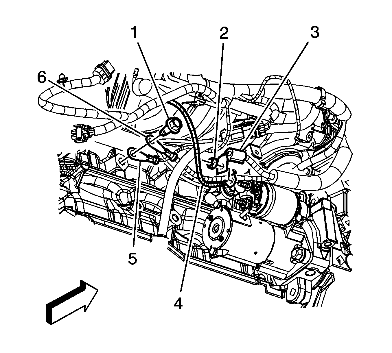
- Remove the engine harness lead (2) from the starter.
- Remove the positive battery cable nut (2) from the starter solenoid.
- Remove the positive battery cable (3) and engine harness terminal (4) from the starter solenoid.
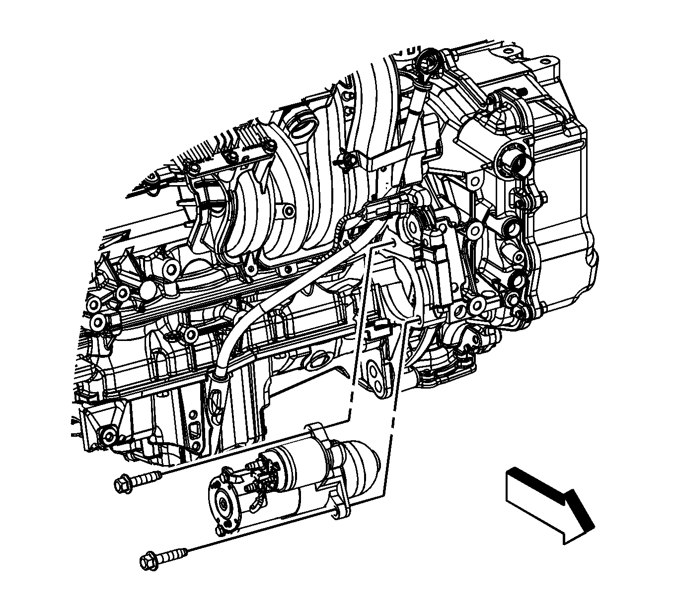
- Remove the starter motor bolts.
- Remove the starter motor.
Installation Procedure
- Install the starter motor.
- Install the starter motor bolts.
- Install the engine harness terminal (4) and positive battery cable (3) to the starter solenoid.
- Install the positive battery cable nut (2) to the starter solenoid.
- Install the engine harness lead (2) to the starter.
- Install the "S" terminal connector to the starter solenoid.
- Lower the vehicle.
- Connect the negative battery cable. Refer to Battery Negative Cable Disconnection and Connection.

Notice: Refer to Fastener Notice in the Preface section.
Tighten
Tighten the bolts to 40 N·m (30 lb ft).

Tighten
Tighten the nut to 10 N·m (89 lb in).

Starter Replacement LZ4
Removal Procedure
- Disconnect the negative battery cable. Refer to Battery Negative Cable Disconnection and Connection .
- Raise the vehicle. Refer to Lifting and Jacking the Vehicle .
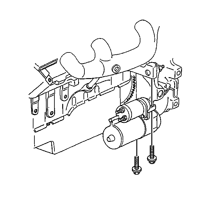
- Remove the flywheel inspection cover bolts.
- Remove the flywheel inspection cover.
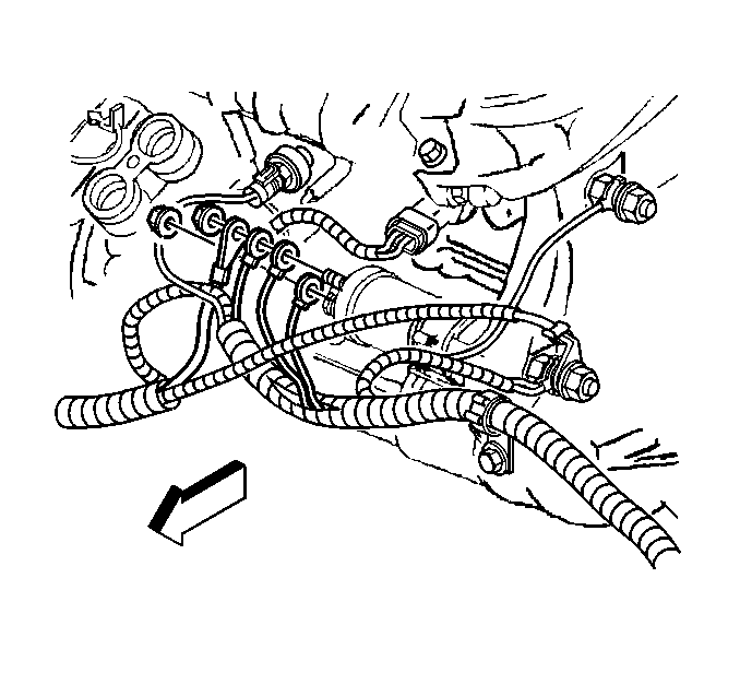
- Remove the electrical connections from the starter motor.
- Remove the starter motor mounting bolts.
- Remove the starter motor.
Installation Procedure
- Install the starter motor to the engine.
- Install the starter motor mounting bolts.
- Install the electrical connection to the battery terminal on the solenoid.
- Install the electrical connections to the S terminal on the solenoid.
- Install the flywheel inspection cover.
- Install the flywheel inspection cover bolts.
- Lower vehicle.
- Connect the negative battery cable. Refer to Battery Negative Cable Disconnection and Connection .
Notice: Before installing the starter motor to the engine, tighten the nut next to the cap on the solenoid BAT terminal. If this terminal is not tight in the solenoid cap, the cap may be damaged during installation of electrical connections and cause the starter motor to fail later.

Notice: Use the correct fastener in the correct location. Replacement fasteners must be the correct part number for that application. Fasteners requiring replacement or fasteners requiring the use of thread locking compound or sealant are identified in the service procedure. Do not use paints, lubricants, or corrosion inhibitors on fasteners or fastener joint surfaces unless specified. These coatings affect fastener torque and joint clamping force and may damage the fastener. Use the correct tightening sequence and specifications when installing fasteners in order to avoid damage to parts and systems.
Tighten
Tighten the bolts to 40 N·m (30 lb ft).

Tighten
Tighten the battery terminal nut to 17 N·m (13 lb ft).
Tighten
Tighten solenoid S terminal nut to 3 N·m (27 lb in).
Tighten
Tighten the flywheel inspection cover bolts to 10 N·m (89 lb in).
Starter Replacement LY7
Removal Procedure
- Disconnect the negative battery cable. Refer to Battery Negative Cable Disconnection and Connection .
- Raise and support the vehicle. Refer to Lifting and Jacking the Vehicle .
- Remove the left catalytic converter. Refer to Catalytic Converter Replacement - Left Side .
- Remove the knock sensor Bank 2. Refer to Knock Sensor Replacement - Bank 2 .
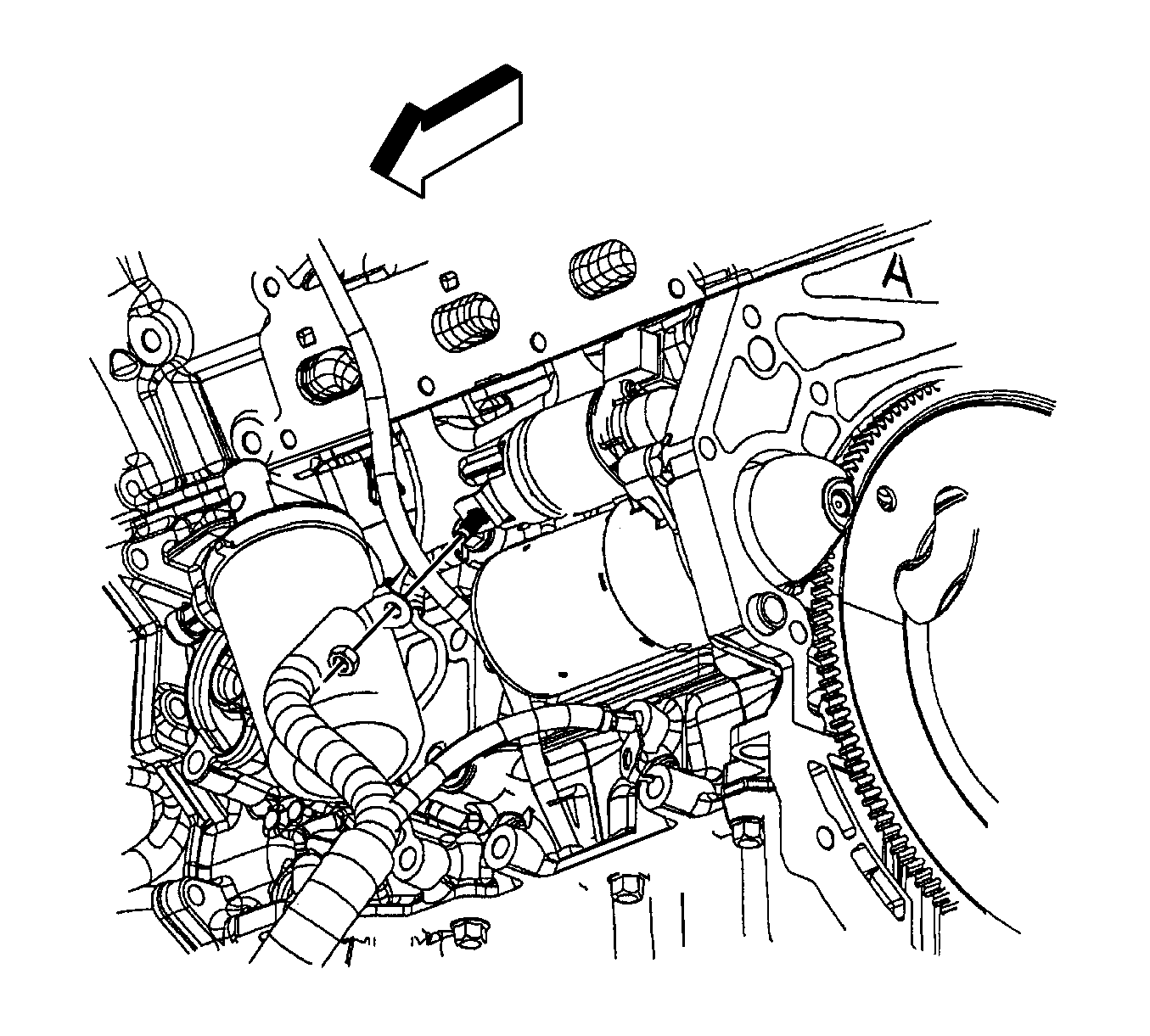
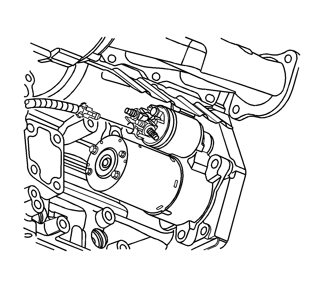
- Remove the starter solenoid BAT terminal nut.
- Disconnect the engine harness electrical connector.
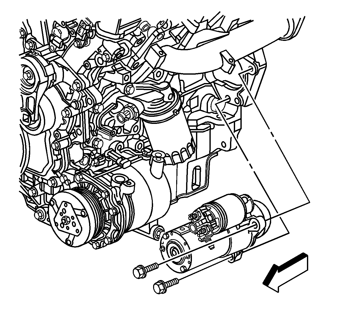
- Disconnect the starter motor bolts and the starter.
Installation Procedure
- Position the starter motor to the engine block.
- Install the starter bolts.
- Connect the electrical connector to the starter.
- Install the starter solenoid BAT terminal nut.
- Install the knock sensor Bank 2. Refer to Knock Sensor Replacement - Bank 2 .
- Install the left catalytic converter. Refer to Catalytic Converter Replacement - Left Side .
- Lower the vehicle.
- Connect the negative battery cable. Refer to Battery Negative Cable Disconnection and Connection .

Notice: Refer to Fastener Notice in the Preface section.
Tighten
Tighten the bolts to 50 N·m (37 lb ft).


Tighten
Tighten the nut to 13 N·m (115 lb in).
Starter Replacement LAT
Removal Procedure
- Disconnect the negative battery cable. Refer to Battery Negative Cable Disconnection and Connection .
- Raise and support the vehicle. Refer to Lifting and Jacking the Vehicle .
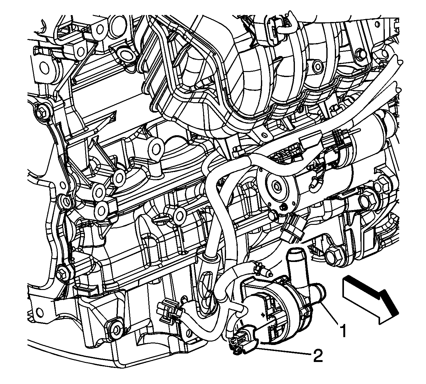
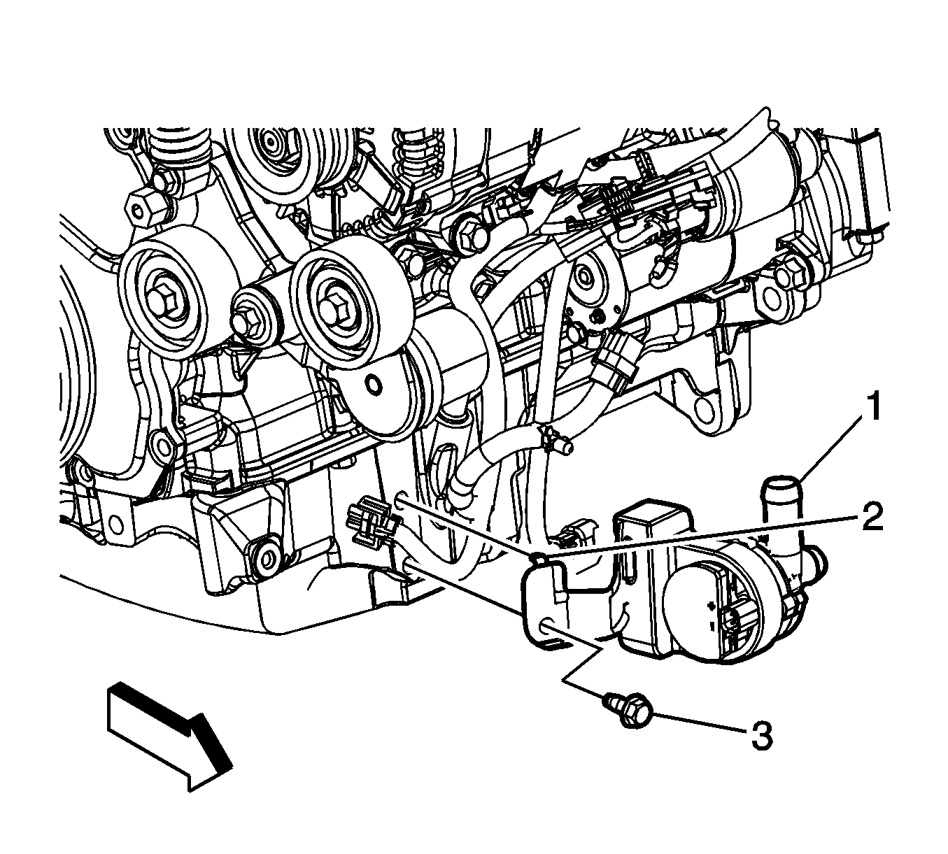
- Disconnect the engine wiring harness electrical connector (2) from the generator control module coolant pump (1).
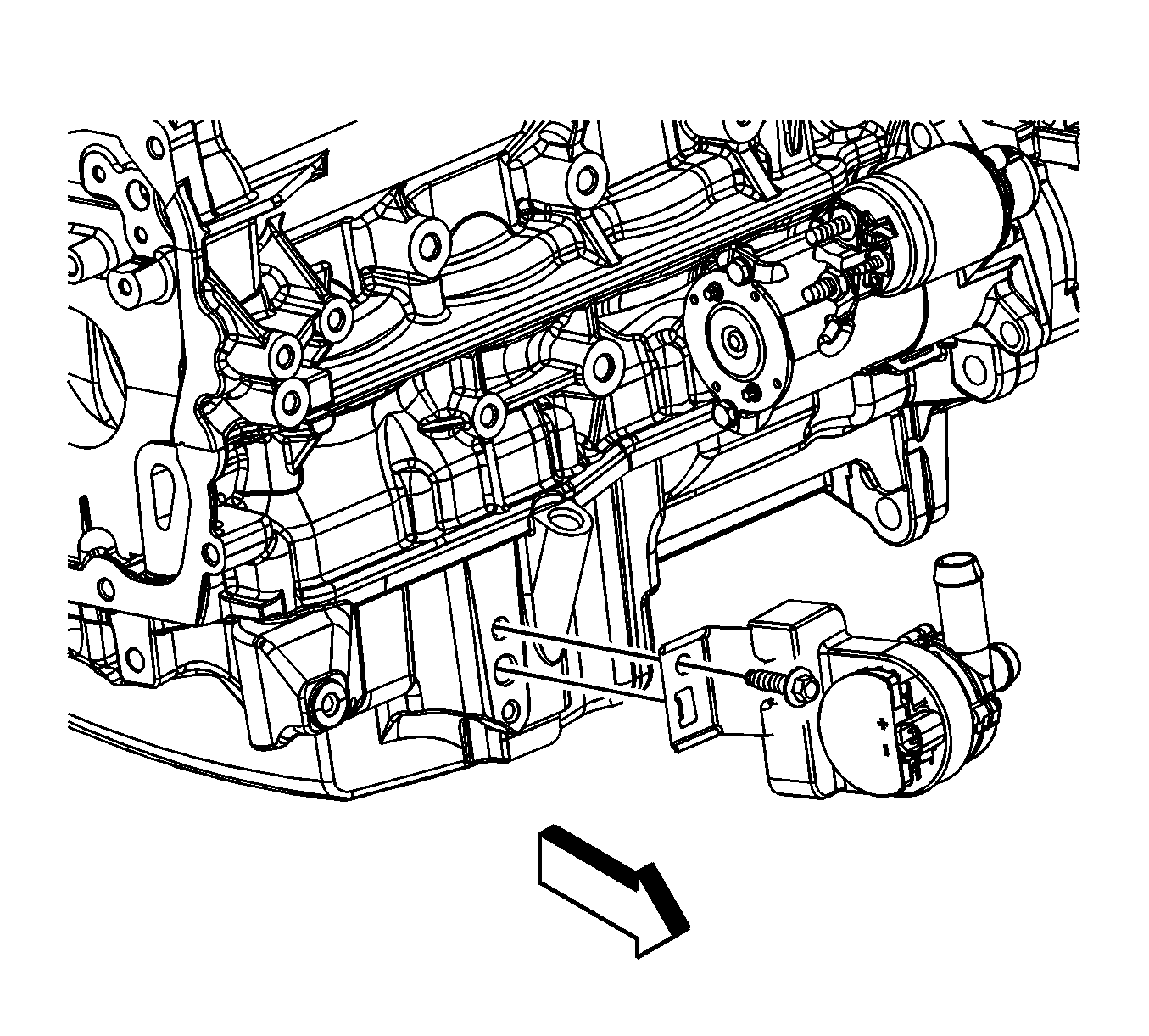
- Remove the generator control module coolant pump bolt (3).
- Remove the generator control module coolant pump (1) (with the hoses attached) from the oil pan.
- Reposition and secure the generator control module coolant pump (with the hoses attached) out of the way.
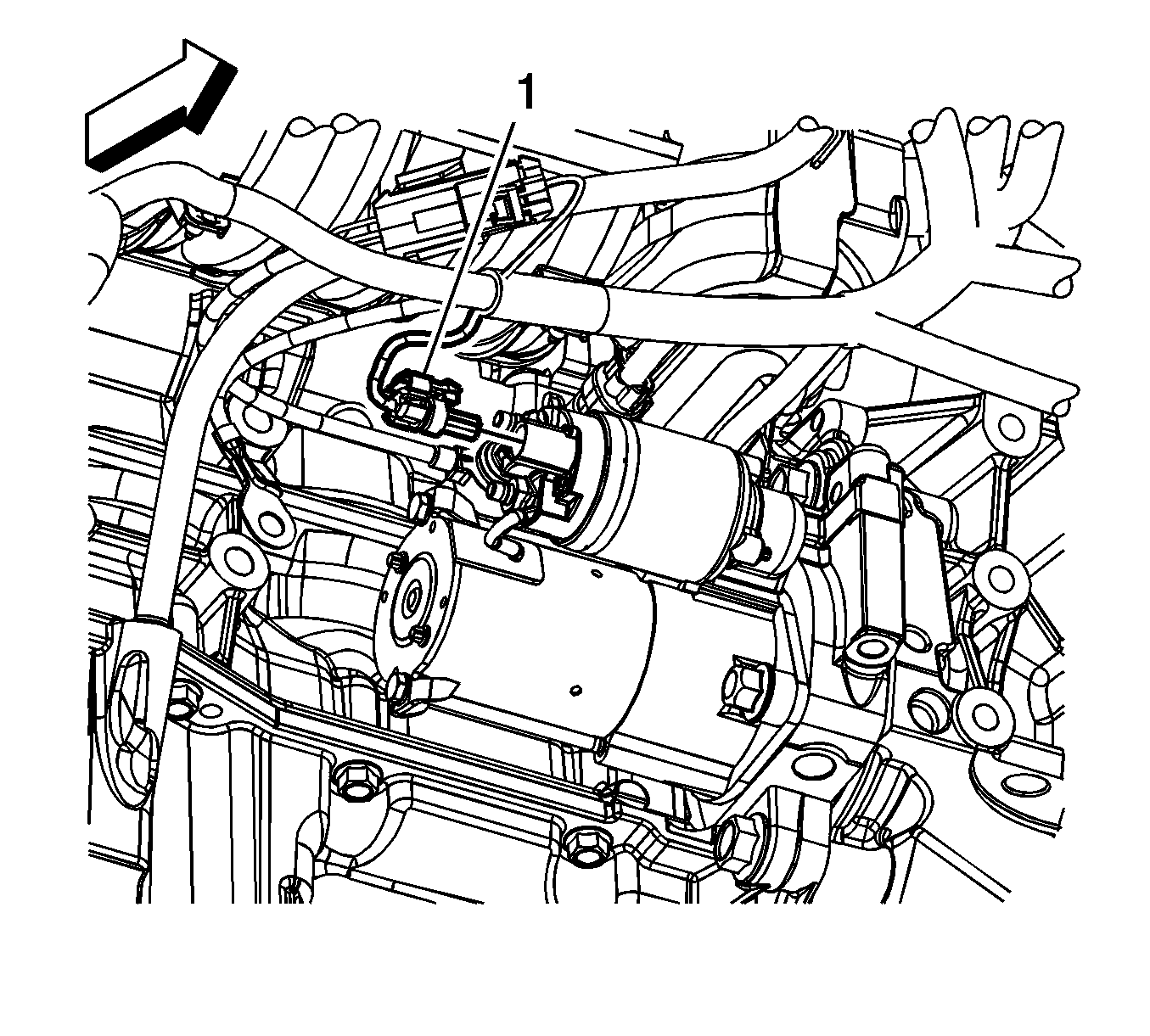
- Disconnect the engine wiring harness electrical connector (1) from the starter.
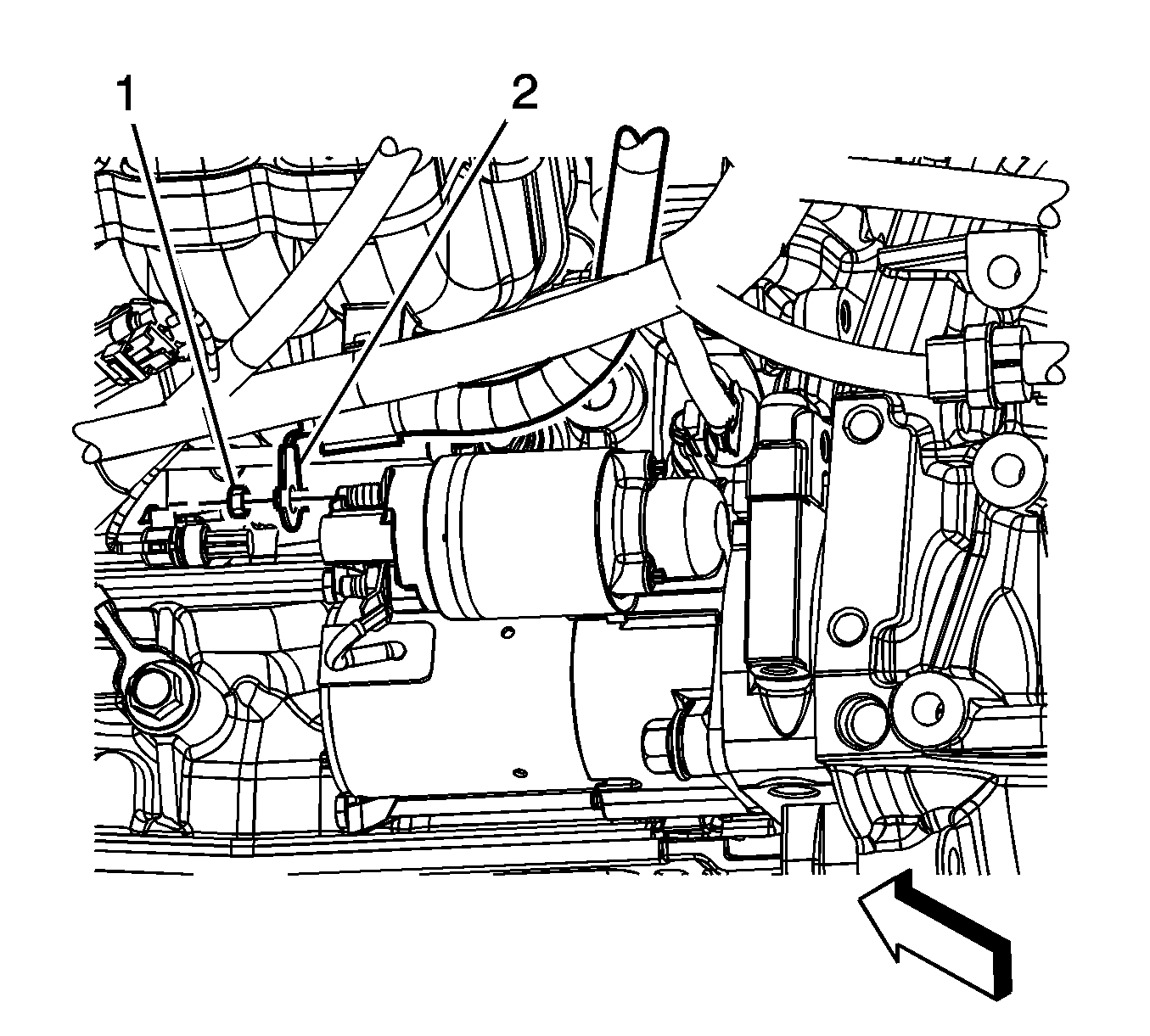
- Remove the positive battery cable to starter motor nut (1).
- Remove the positive battery cable lead (2) from the starter motor.
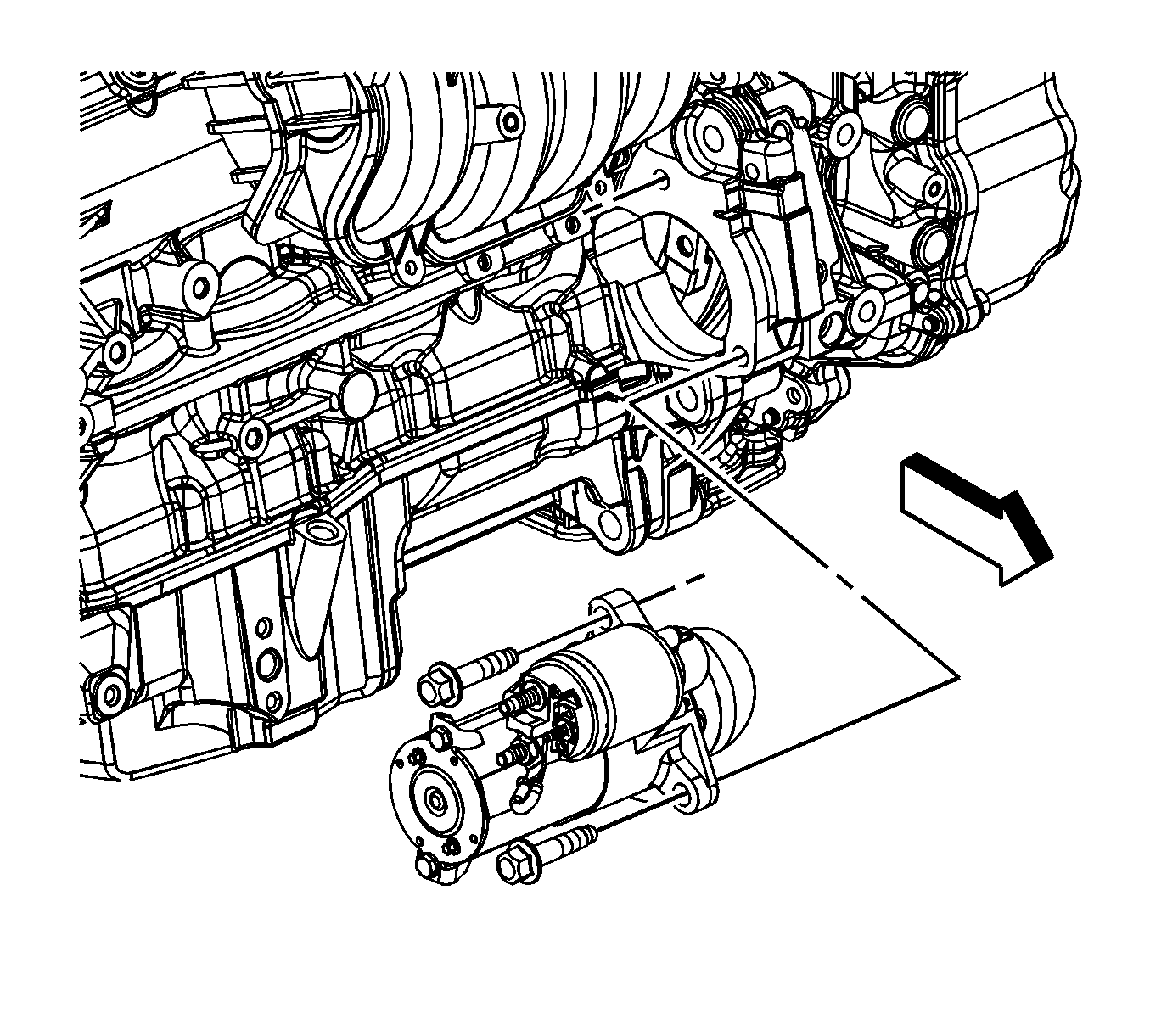
- Remove the starter motor bolts and starter.
Installation Procedure
- Install the starter motor and bolts.
- Install the positive battery cable lead (2) to the starter motor.
- Install the positive battery cable to starter motor nut (1).
- Connect the engine wiring harness electrical connector (1) to the starter.
- Unsecure the generator control module coolant pump.
- Position the generator control module coolant pump (1) (with the hoses attached) to the oil pan. Ensure that the anti-rotation tab (2) is inserted into the hole in the oil pan.
- Install the generator control module coolant pump bolt (3).
- Connect the engine wiring harness electrical connector (2) to the generator control module coolant pump (1).
- Lower the vehicle.
- Connect the negative battery cable. Refer to Battery Negative Cable Disconnection and Connection .
Notice: Refer to Fastener Notice in the Preface section.

Tighten
Tighten the bolts to 53 N·m (39 lb ft).

Tighten
Tighten the nut to 10 N·m (89 lb in).

Tighten
Tighten the bolt to 22 N·m (16 lb ft).

