Removal Procedure
Notice: Use care when handling the coolant sensor. Damage to the coolant sensor will affect the operation of the fuel control system.
- Drain the cooling system. Refer to Cooling System Draining and Filling .
- Remove the intake manifold cover, if necessary. Refer to Intake Manifold Cover Replacement .
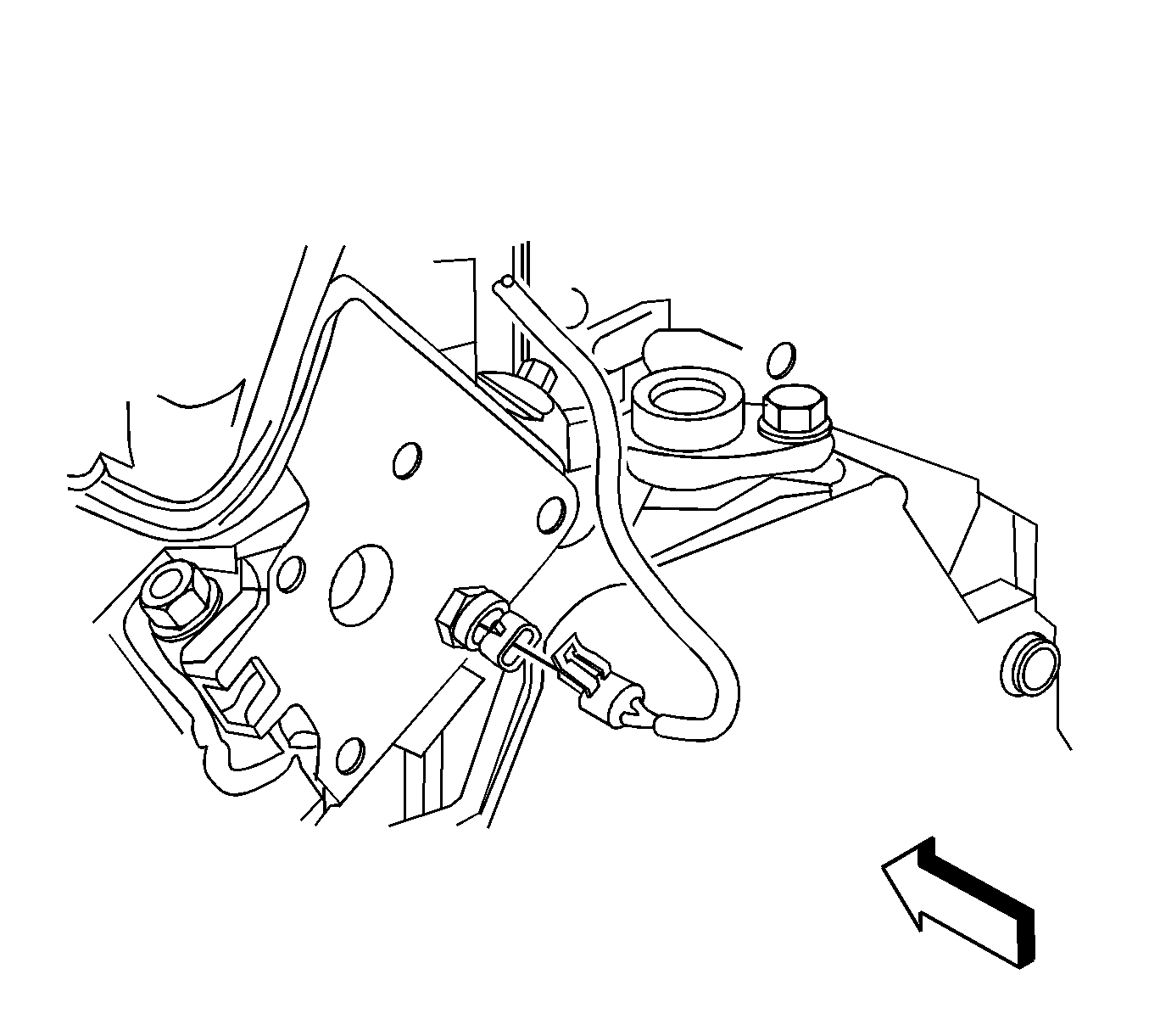
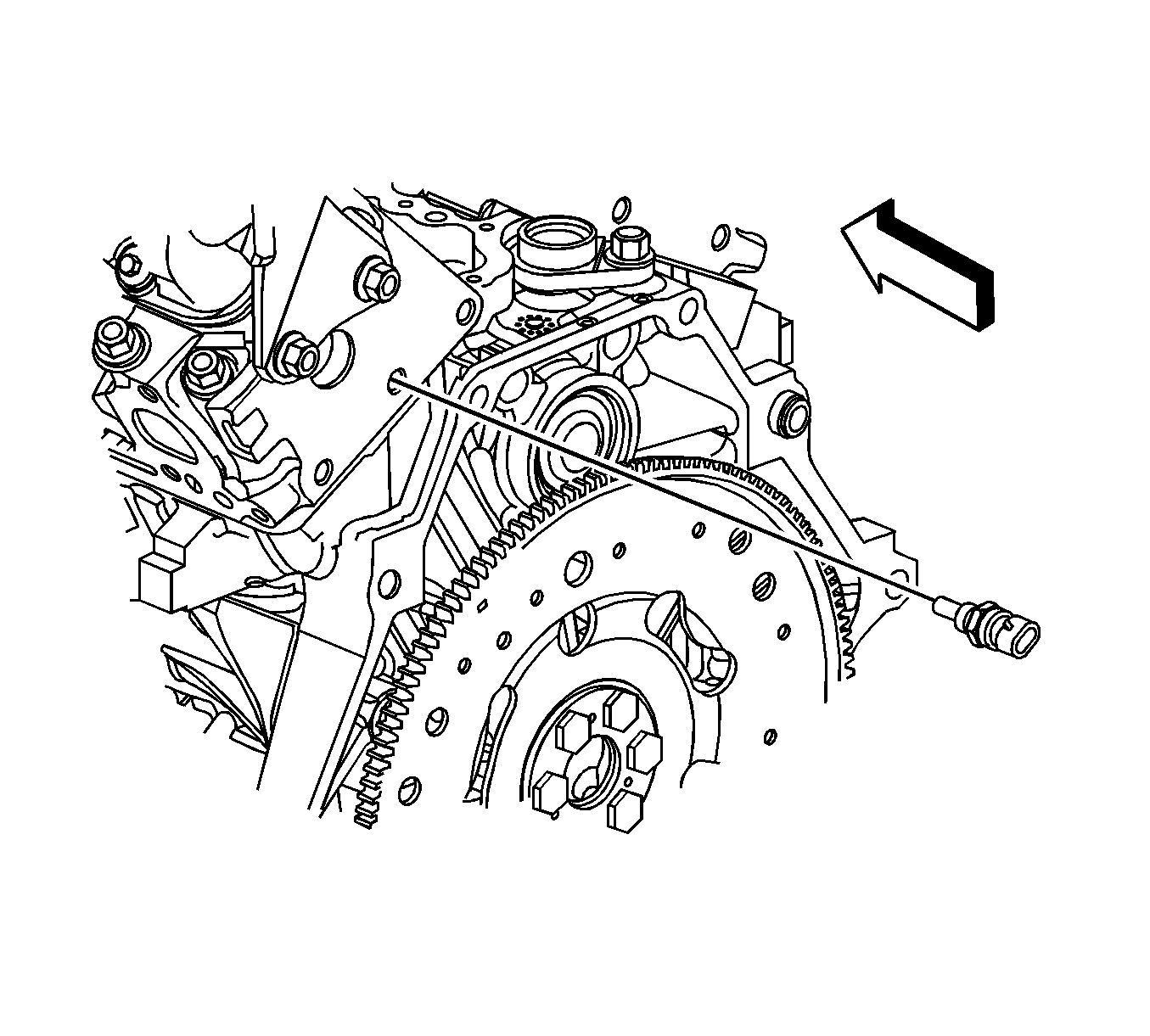
- Disconnect the fuel injector wiring harness electrical connector from the engine coolant temperature (ECT) sensor.
- Remove the ECT sensor.
Installation Procedure
Notice: Replacement components must be the correct part number for the application. Components requiring the use of the thread locking compound, lubricants, corrosion inhibitors, or sealants are identified in the service procedure. Some replacement components may come with these coatings already applied. Do not use these coatings on components unless specified. These coatings can affect the final torque, which may affect the operation of the component. Use the correct torque specification when installing components in order to avoid damage.
- Coat the threads of the ECT sensor with sealer GM P/N 13246004 (Canadian P/N 10953480) or equivalent.
- Install the ECT sensor.
- Connect the fuel injector wiring harness electrical connector to the ECT sensor.
- Install the intake manifold cover, if necessary. Refer to Intake Manifold Cover Replacement .
- Fill the cooling system. Refer to Cooling System Draining and Filling .
Notice: Refer to Fastener Notice in the Preface section.
Tighten
Tighten the sensor to 20 N·m (15 lb ft).
