Tools Required
| • | J 24420-C Harmonic Balancer Puller |
| • | J 29113 Crankshaft Balancer Installer |
Removal Procedure
- Remove the drive belt. Refer to Drive Belt Replacement .
- Raise and support the vehicle. Refer to Lifting and Jacking the Vehicle in General Information.
- Remove the right front tire and wheel. Refer to Tire and Wheel Removal and Installation in Tires and Wheels.
- Remove the right front fender liner. Refer to Front Fender Liner Replacement in Body Front End.
- Remove the flywheel inspection cover.
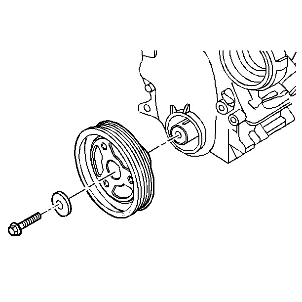
- Remove the balancer retaining bolt. Use an assistant to keep the flywheel from turning.
- Install J 24420-C on the balancer.
- Turn the puller screw.
- Remove the balancer.
Notice: The inertial weight section of the balancer is assembled to the hub with a rubber type material. The correct removal procedure must be followed or movement of the inertial weight section of the hub will destroy the tuning of the balancer.
Installation Procedure
- Coat the front cover seal contact area with engine oil.
- Apply sealant to the crankshaft key. Apply sealant to the crankshaft keyway. Use RTV sealant GM P/N 1052917 or the equivalent.
- Place the balancer into position over the key in the crankshaft.
- Install J 29113 onto the crankshaft.
- Pull the balancer into position.
- Remove J 29113 from the balancer.
- Install the balancer retaining bolt. Use an assistant to keep the flywheel from turning.
- Install the flywheel inspection cover.
- Install the right front fender liner. Refer to Front Fender Liner Replacement in Body Front End.
- Install the right tire and wheel. Refer to Tire and Wheel Removal and Installation in Tires and Wheels.
- Lower the vehicle.
- Install the drive belt. Refer to Drive Belt Replacement .
- Perform the crankshaft position learn variation procedure. Refer to Crankshaft Position System Variation Learn in Engine Controls - 3.1L.
Notice: Use the correct fastener in the correct location. Replacement fasteners must be the correct part number for that application. Fasteners requiring replacement or fasteners requiring the use of thread locking compound or sealant are identified in the service procedure. Do not use paints, lubricants, or corrosion inhibitors on fasteners or fastener joint surfaces unless specified. These coatings affect fastener torque and joint clamping force and may damage the fastener. Use the correct tightening sequence and specifications when installing fasteners in order to avoid damage to parts and systems.
Tighten
Tighten the bolt to 70 N·m (52 lb ft) plus and additional 72 degrees.
