Important: Brake disc thickness variation MUST be inspected BEFORE inspecting for assembled lateral runout (LRO). Thickness variation exceeding the maximum acceptable level can cause brake pulsation. Refer to Brake Rotor Thickness Variation Measurement.
Important: Brake disc and hub indexing is required so the minimum installed brake disc runout is achieved. Brake disc and hub indexing involves aligning the point of maximum runout on the hub with the point of least runout on the brake disc.
Important: The procedure is to be used when installing NEW brake discs or brake discs that have been removed for any reason and where the brake disc to hub matching is not evident.
The procedure consists of three parts:
| • | Clean Mating Surfaces. |
| • | Indexing Brake Disc to Hub. If these measurements are not within specification, go to Hub Runout Inspection. |
| • | Hub Runout Inspection. |
Clean Mating Surfaces
- Raise and support the vehicle. Refer to Lifting and Jacking the Vehicle.
- Remove wheels. Refer to Tire and Wheel Removal and Installation.
- Remove the brake caliper. Refer to Front Brake Rotor Replacement or Rear Brake Rotor Replacement.
- Make sure that brake disc and hub mating surfaces are free from dirt, corrosion, etc. If required, use fine emery paper to clean surfaces.
Caution: Refer to Safety Glasses Caution in the Preface section.
Caution: Refer to Vehicle Lifting Caution in the Preface section.
Caution: Refer to Brake Dust Caution in the Preface section.
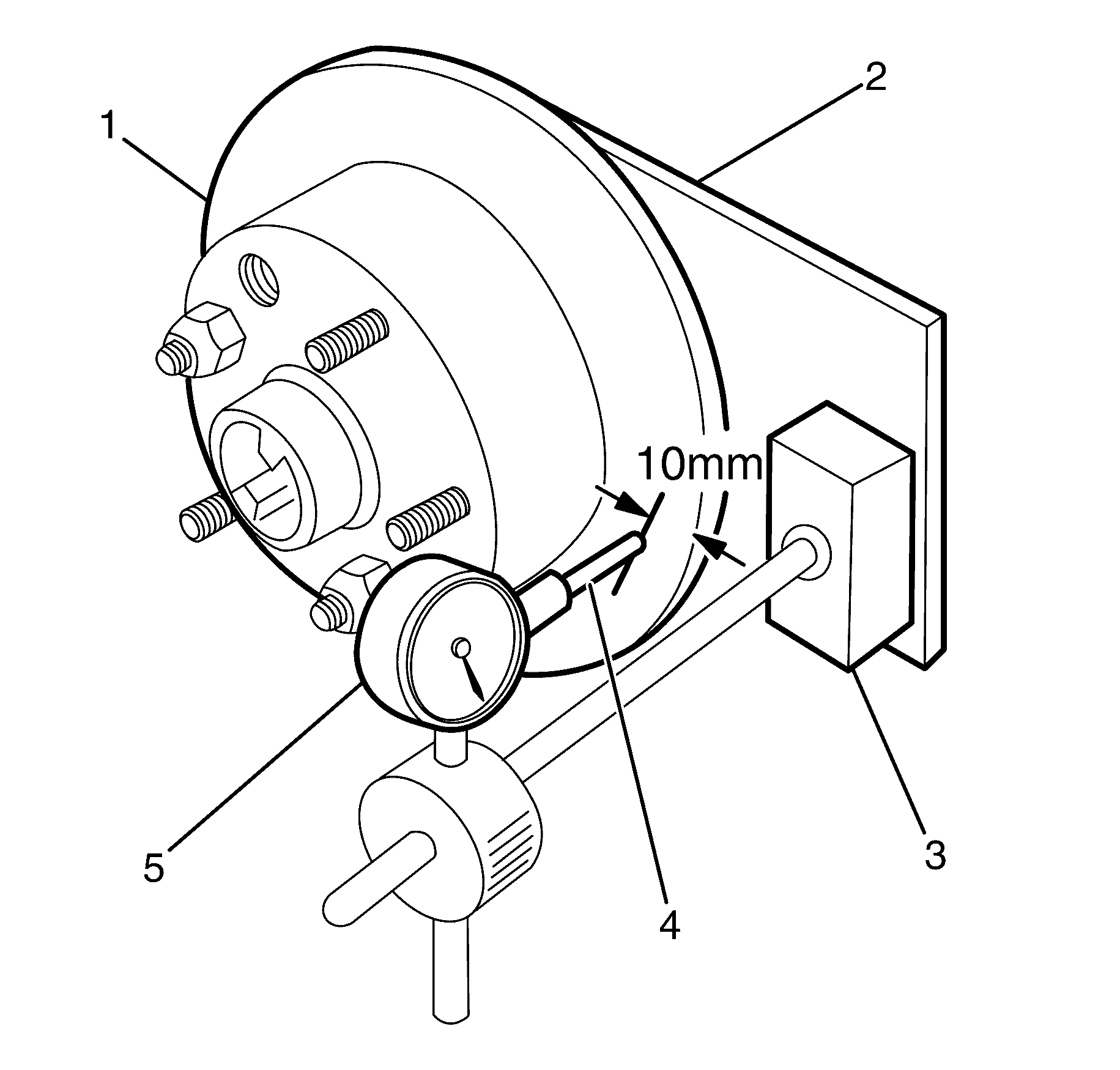
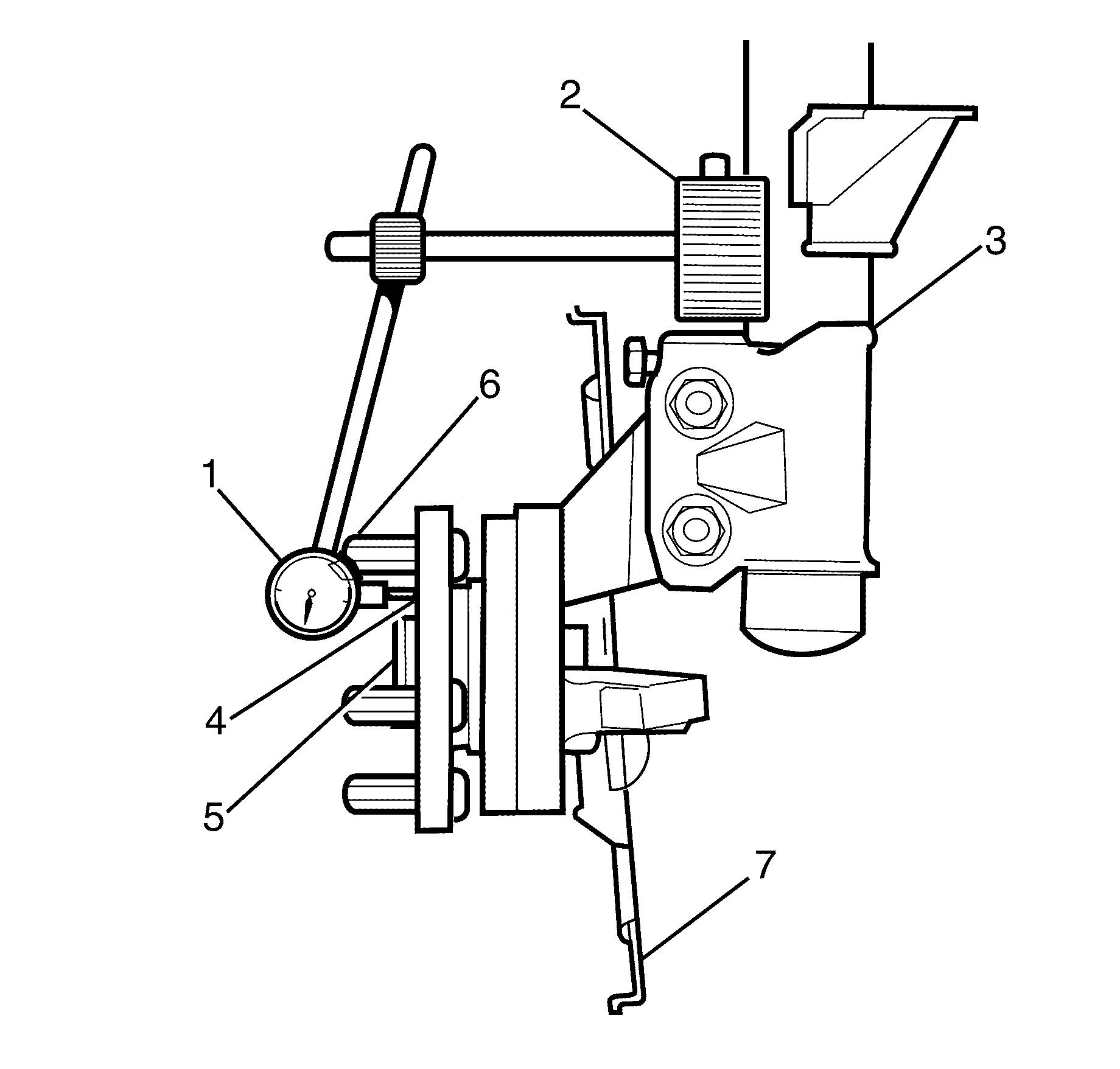
Indexing Brake Disc to Hub - Front
- Install 2 wheel nuts in reverse to opposite wheel studs to retain the brake disc to the hub.
- Number each of the wheel stud holes on the front surface of the brake disc from 1 to 5.
- Place a chalk mark on the end of the wheel stud adjacent to the number "1" hole (1).
- Set up a dial indicator (2) on a magnetic base (4) and attach to the front strut unit (5) above the brake disc (1).
- Position the pointer (3) about 10 mm (3/8 in), from the outer edge of the disc.
- Rotate the brake disc (1) and note the points of minimum and maximum runout on the dial indicator (2).
- Record the figure together with the number on the brake disc aligned with the chalk-marked stud.
- Remove and reinstall the brake disc with hole number '2' over the marked stud. Repeat Steps 4 to 7. This procedure is to be repeated for all 5 hole positions.
- Mount the brake disc to the hub in the stud position which recorded the least amount of runout.
Caution: Refer to Safety Glasses Caution in the Preface section.
Caution: Refer to Vehicle Lifting Caution in the Preface section.
Caution: Refer to Brake Dust Caution in the Preface section.
Important: The number of divisions between the points of minimum and maximum runout on the dial indicator is the total indicated runout.
Important: If the lowest assembled disc runout achieved is more than 0.05 mm (50 micron), then the hub runout should be inspected as detailed in the Hub Runout procedure.
Specification
The maximum assembled brake disc and hub runout
at brake disc outer diameter equals 0.05 mm.
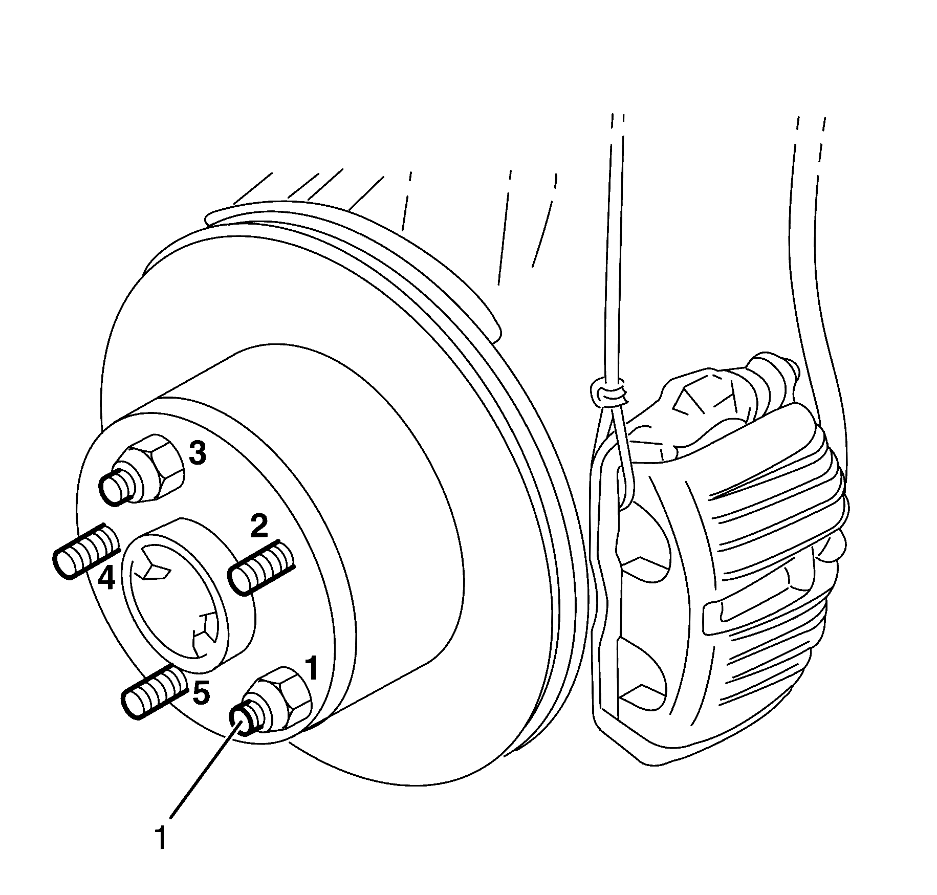
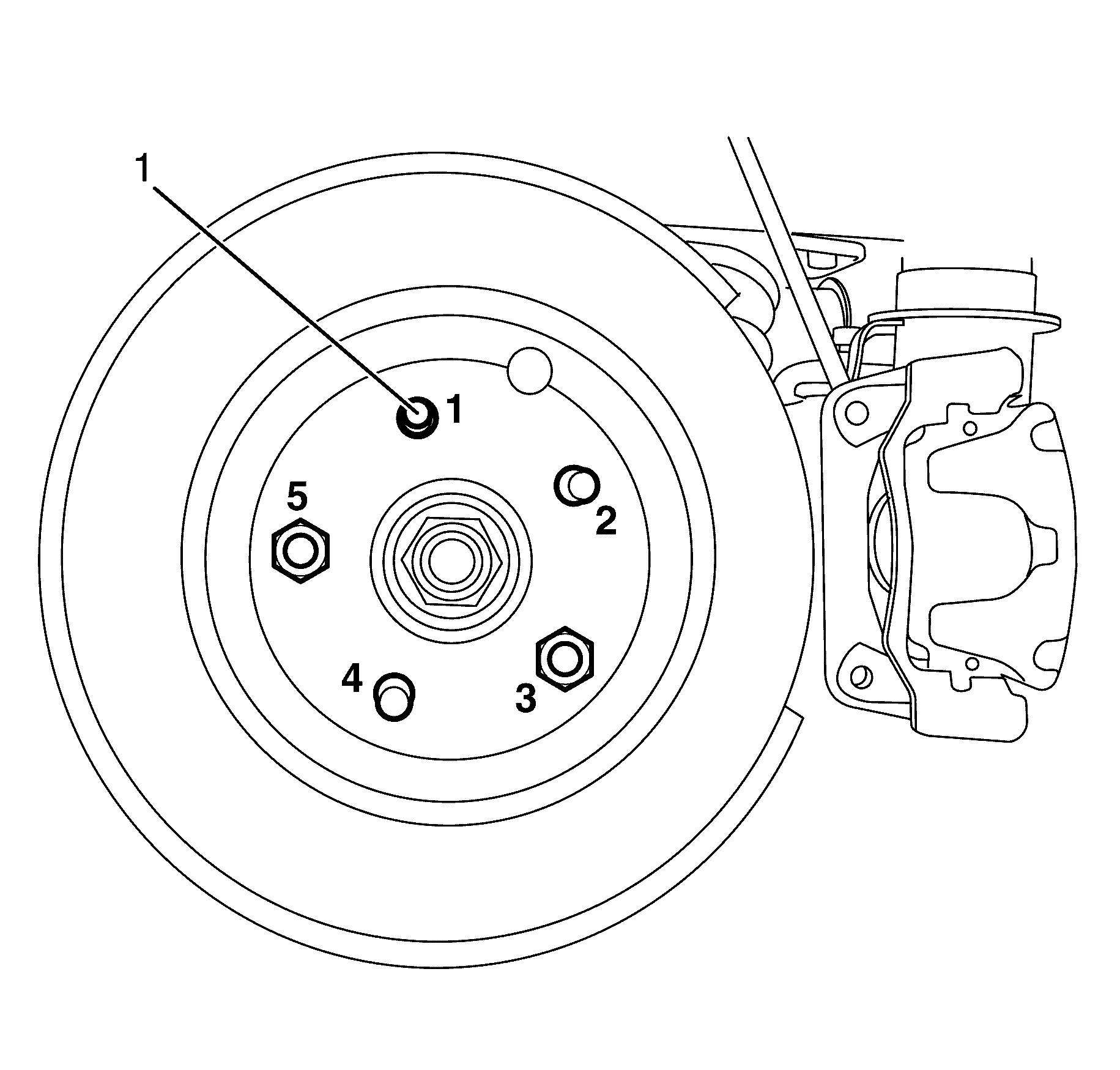
Index Brake Disc to Hub - Rear
- Install 2 wheel nuts in reverse to opposite wheel studs to retain the brake disc to the hub.
- Number each of the wheel stud holes on the front surface of the brake disc from 1 to 5.
- Place a chalk mark on the end of the wheel stud adjacent to the number "1" hole (1).
- Bolt the dial indicator plate (3) to the brake caliper attaching points on the rear knuckle. Refer to Dial Indicator Plate in Special Tools for dial indicator plate details.
- Set up a dial indicator (1) on a magnetic mounting base (2) and attach to the dial indicator plate (3).
- Position the pointer (4) about 10 mm (3/8 in), from the outer edge of the brake disc (5).
- Carefully rotate the brake disc and note the points of minimum and maximum runout on the dial indicator.
- Record this figure together with the number on the brake disc aligned with the chalk-marked stud.
- Remove and reinstall brake disc with hole number 2 over the marked stud and repeat Step 4. This procedure is to be repeated for all 5 hole positions.
Caution: Refer to Safety Glasses Caution in the Preface section.
Caution: Refer to Vehicle Lifting Caution in the Preface section.
Caution: Refer to Brake Dust Caution in the Preface section.
Important: The number of divisions between the points of minimum and maximum runout on the dial indicator is the total indicated runout.
Important: If the lowest assembled brake disc runout achieved is more than 0.05 mm (50 micron), then the trunnion hub runout should be inspected as detailed in the Hub Runout procedure.
Specification
Maximum assembled brake disc and hub runout
at brake disc outer diameter [dash ] rear brake disc: 0.05 mm
Mount the brake disc to the hub in the stud position which recorded the least amount of runout.
Hub Runout Inspection - Front
Caution: Refer to Safety Glasses Caution in the Preface section.
Caution: Refer to Vehicle Lifting Caution in the Preface section.
Caution: Refer to Brake Dust Caution in the Preface section.
- Clean the front hub face with fine emery paper.
- Locate the dial indicator magnetic base (2) on the front strut unit (3) and position the pointer (4) on the hub face midway between the spigot (5) and the studs (6).
- Rotate the hub by the hub spigot (5) (to avoid loading the bearing) and note the points of minimum and maximum runout on the dial indicator (1).
- If the runout measured in Step 3 exceeds 0.025 mm (25 micron), replace the hub unit. Refer to Front Wheel Bearing and Hub Replacement.
Important: For this inspection to be performed with 100 percent accuracy, a flat parallel surface plate attached to the hub should be used. However, measuring runout between spigot (5) and the studs (6) should yield adequate results.
Important: The number of divisions between the points of minimum and maximum runout on the dial indicator (1) is the total indicated runout.
Important: The maximum runout at hub face-front hub is 0.025 mm.
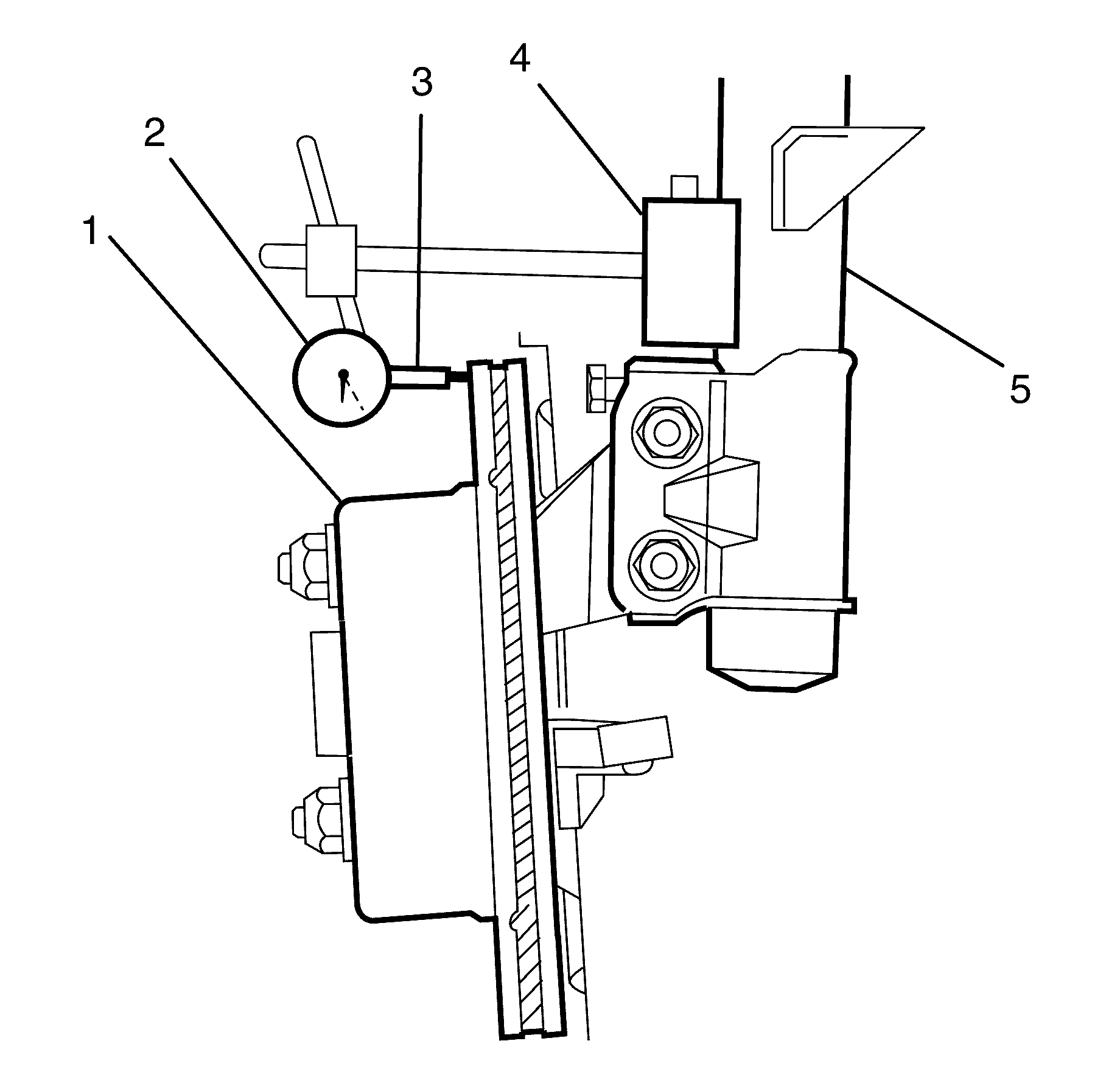
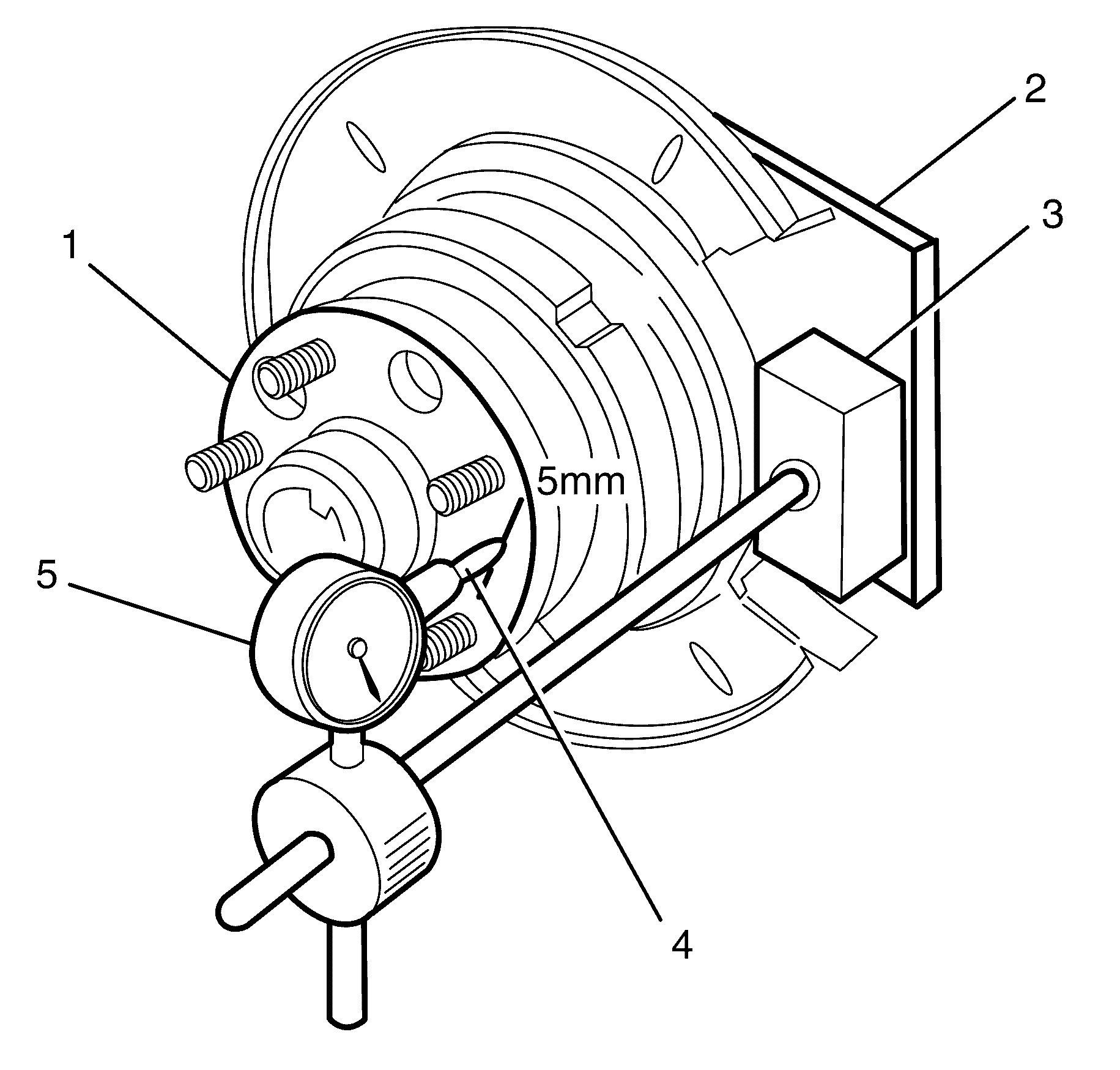
Hub Runout Inspection - Rear
- Clean the hub face by rubbing lightly with fine emery paper.
- Set up a dial indicator (5) on a magnetic base (3) and attach to the pre-fabricated mounting plate (2).
- Position the pointer (4) on the hub face 5 mm (0.2 in) from the edge of the hub (1).
- Rotate the hub by the wheel studs and note the points of minimum and maximum runout on the dial indicator (5).
- If the runout measured in Step 3 exceeds 0.025 mm (25 micron), replace the hub assembly.
Caution: Refer to Safety Glasses Caution in the Preface section.
Caution: Refer to Vehicle Lifting Caution in the Preface section.
Caution: Refer to Brake Dust Caution in the Preface section.
Important: For this inspection to be performed with 100 percent accuracy, a flat parallel surface plate attached to the hub should be used. However, measuring runout on the hub face 5 mm (0.2 in) from the edge of the hub (1) should yield adequate results.
Important: The number of divisions between the points of minimum and maximum runout on the dial indicator (5) is the total indicated runout.
Specification
Maximum hub total indicated runout (TIR):
0.25 mm
