GM Service Manual Online
For 1990-2009 cars only
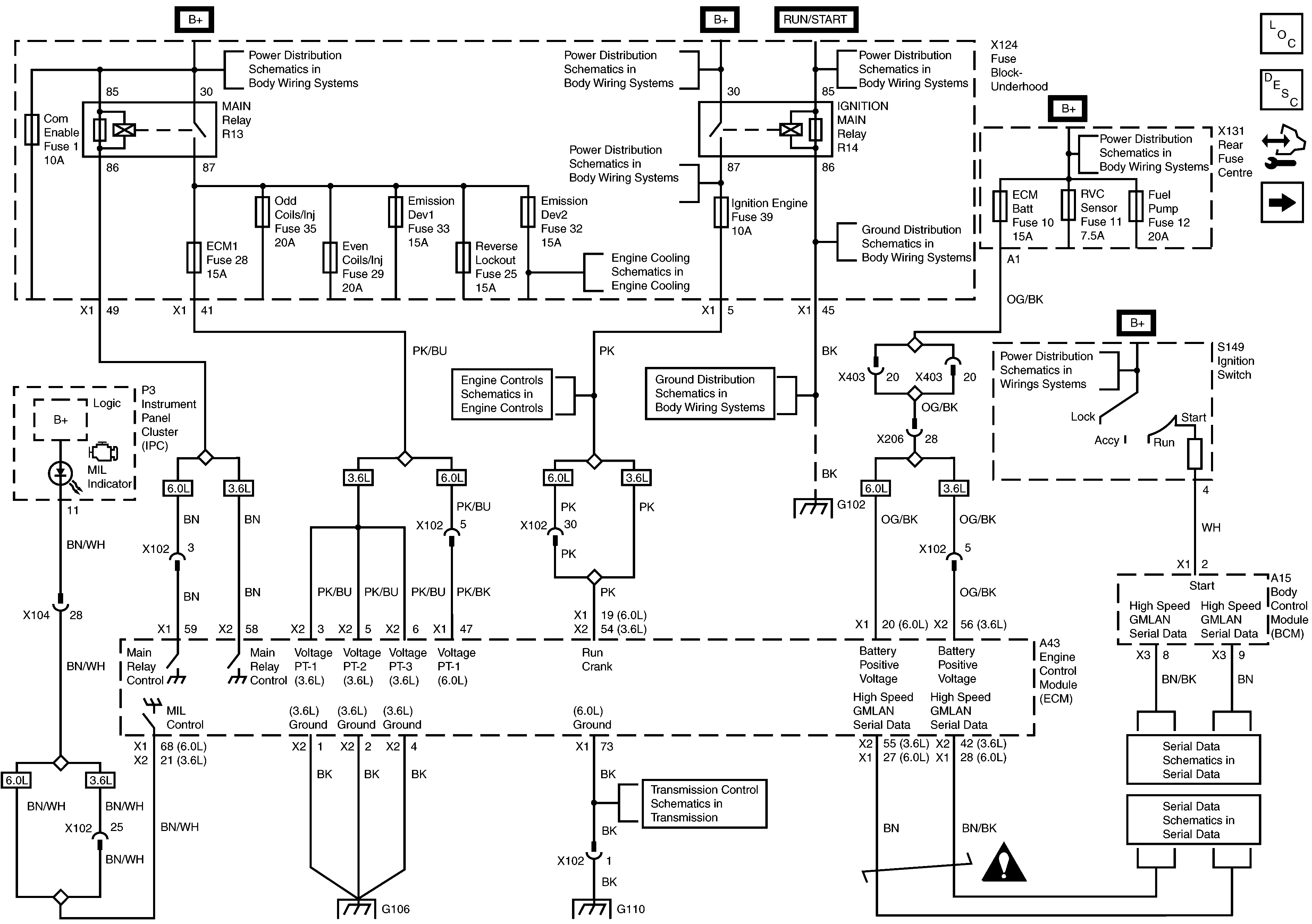
Figure 1:

ECM Power, Ground and Serial Data


Object Number: 1962309  Size: FS
Master Electrical Component List
Engine Control Module Description
Control Module References
ECM Power, Ground and Serial Data
G103, G110, G111 and G112 (6.0L)
G101 and G102
G103, G110, G111 and G112 (6.0L)
Pin Allocation
Pin Allocation
TCM and Transmission, Power, Ground, Serial Data, Inputs and Outputs
G101 and G102
Cooling Fans and Relays
B+ Bus - 1 of 2
B+ Bus - 1 of 2
B+ Bus - 1 of 2
B+ Bus - 1 of 2
ECM, Fuel Pump, Rear Main, RVC Sense and Trailer Fuses
B+ Bus - 2 of 2
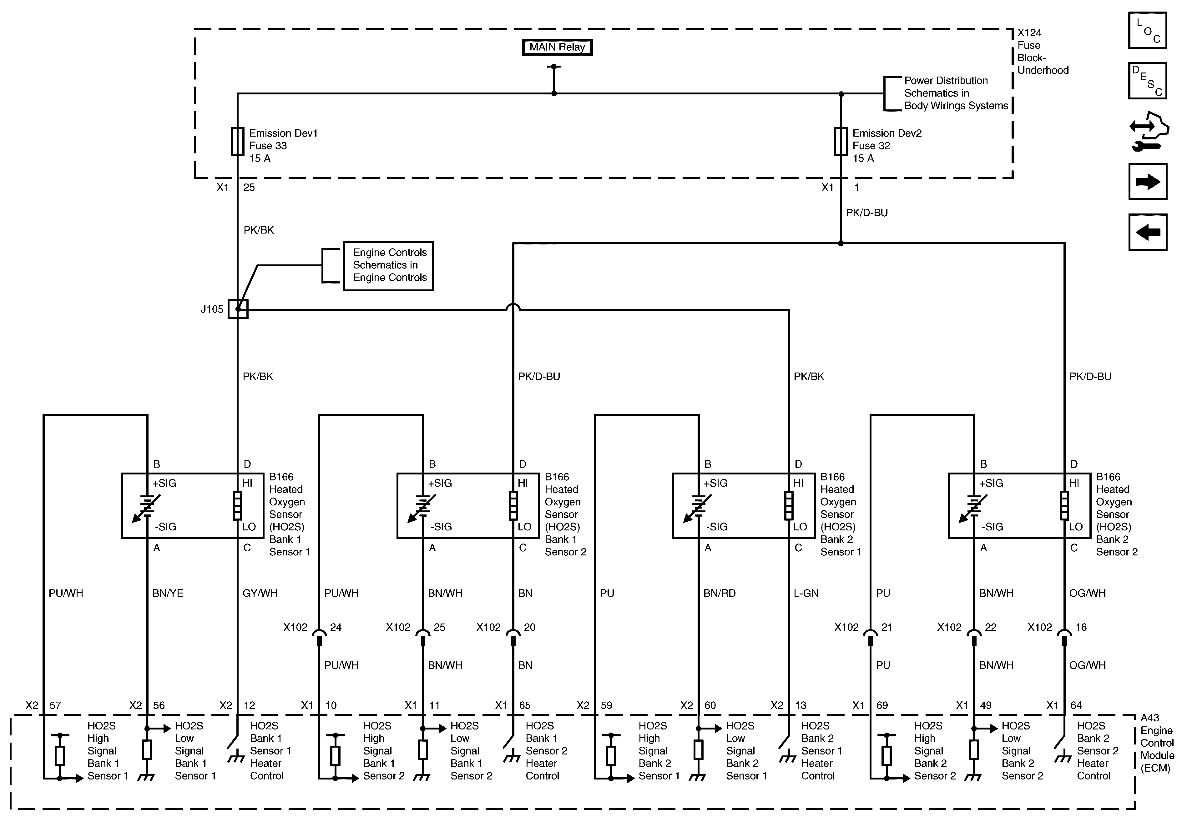
Figure 2:

Heated Oxygen Sensors


Object Number: 1962333  Size: FS
Master Electrical Component List
Engine Control Module Description
Control Module References
Camshaft Position Sensor, MAP Sensor, Reverse Lockout Solenoid, Evap Canister Purge Solenoid, Coolant Temp Sensor, MAF Sensor, Oil Level and Temp Sensor and Backup Lamp Switch
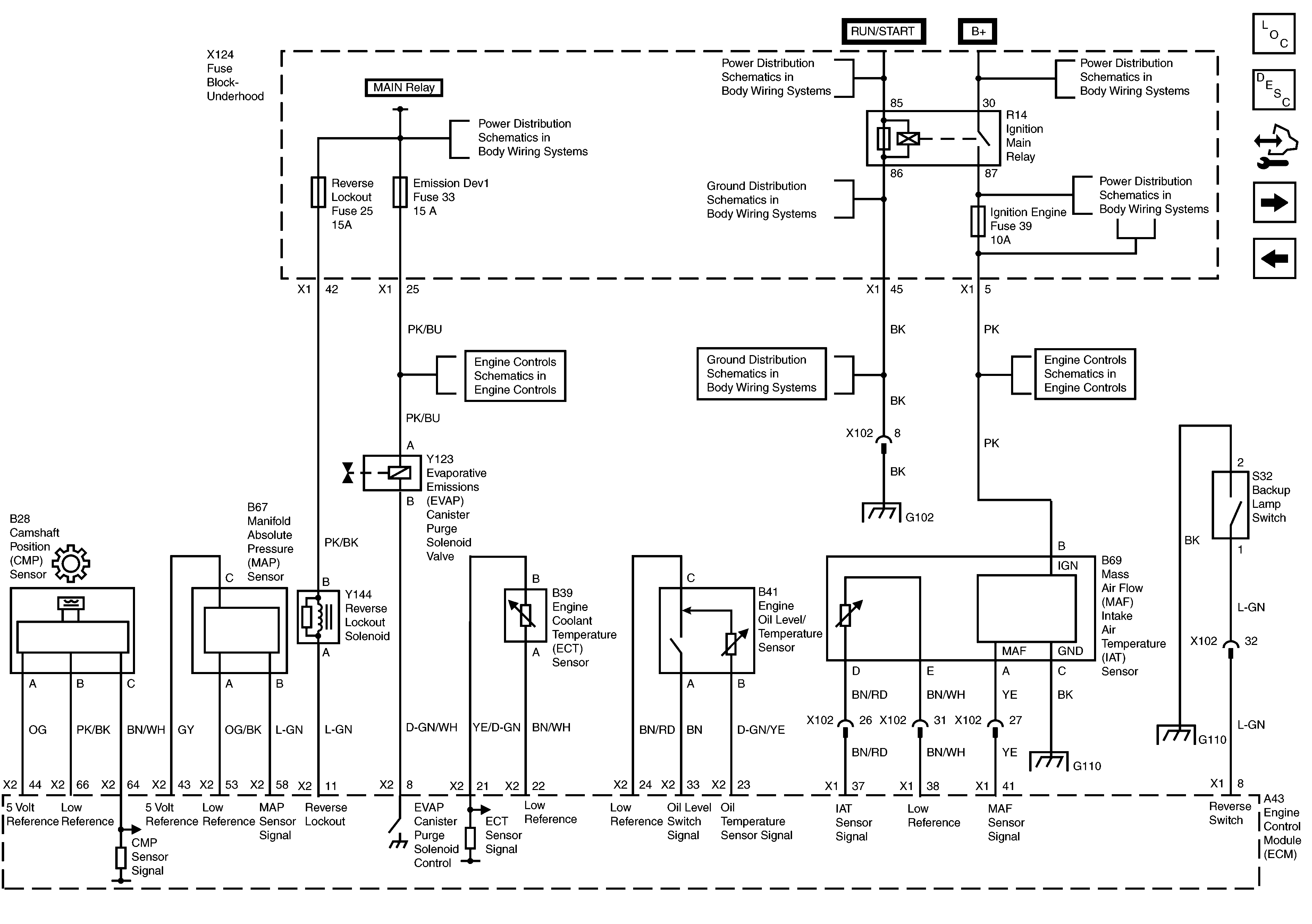
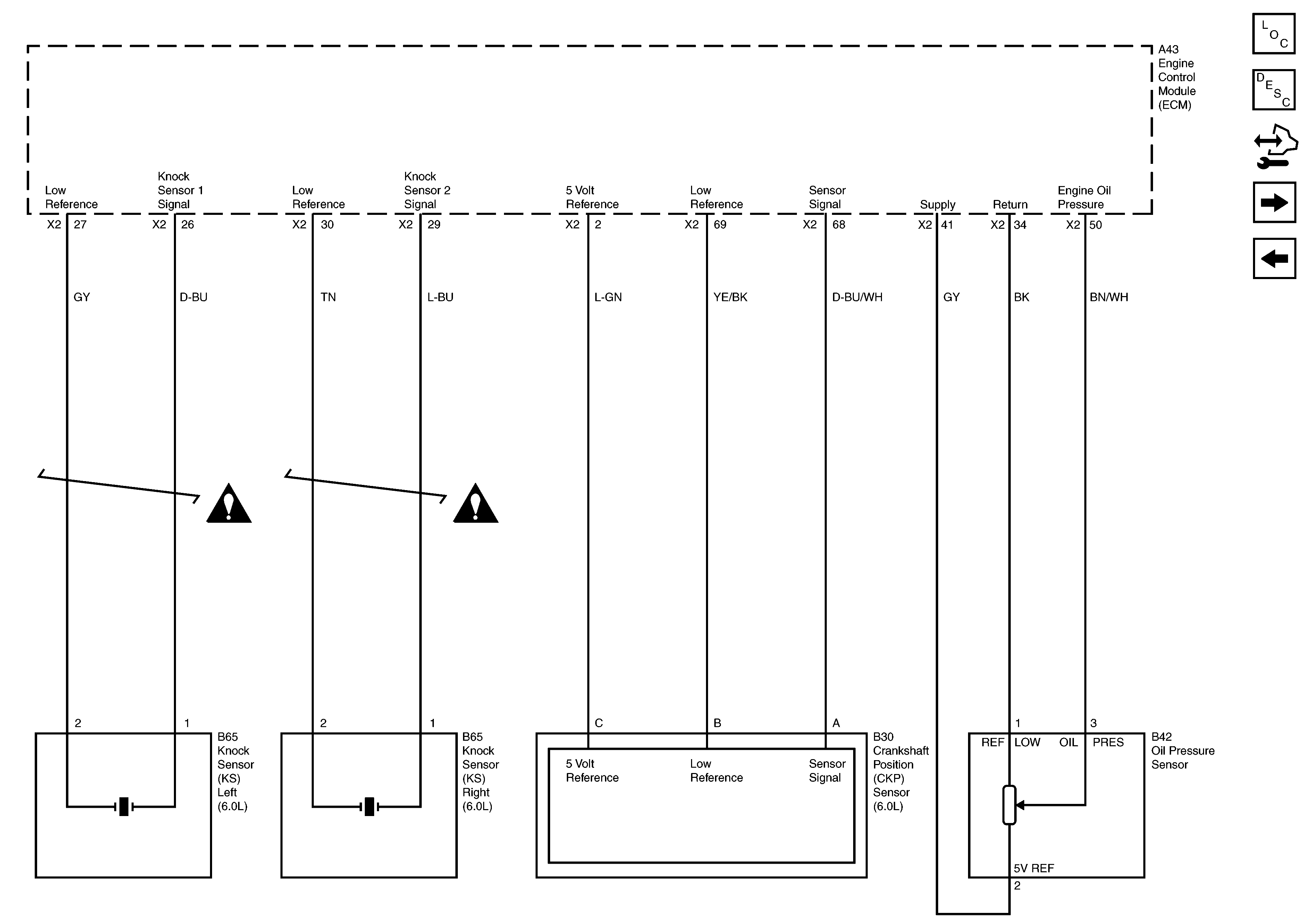
Crankshaft Position and Knock Sensors
ECM Power, Ground and Serial Data
Batt Main 1, Courtesy Lights, Instrument/Ctr Display/RFA/DLC, Turn Signal Left and Turn Signal Right Fuses and Window Batt Circuit Breakers
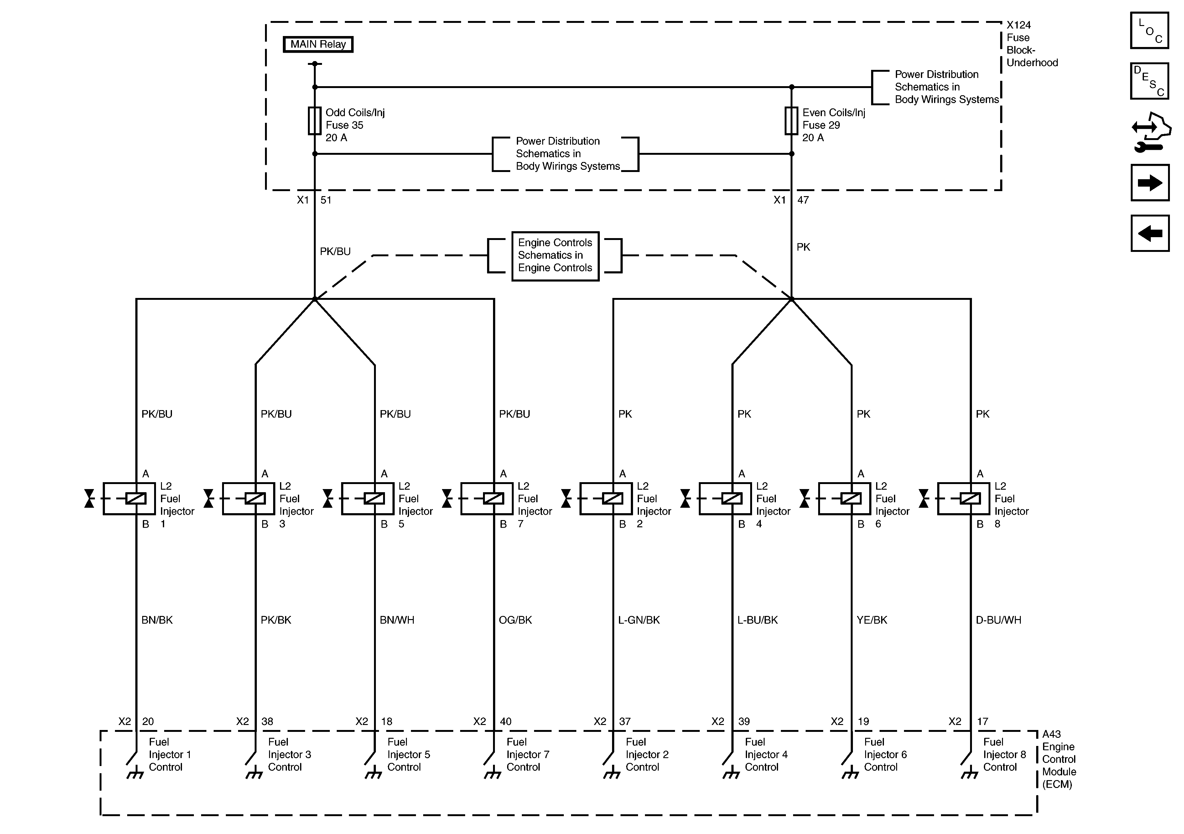
Figure 3:

Fuel Injectors


Object Number: 1962328  Size: FS
Master Electrical Component List
Engine Control Module Description
Control Module References
Odd Ignition Coils
ECM Power, Ground and Serial Data
B+ Bus - 1 of 2
B+ Bus - 1 of 2
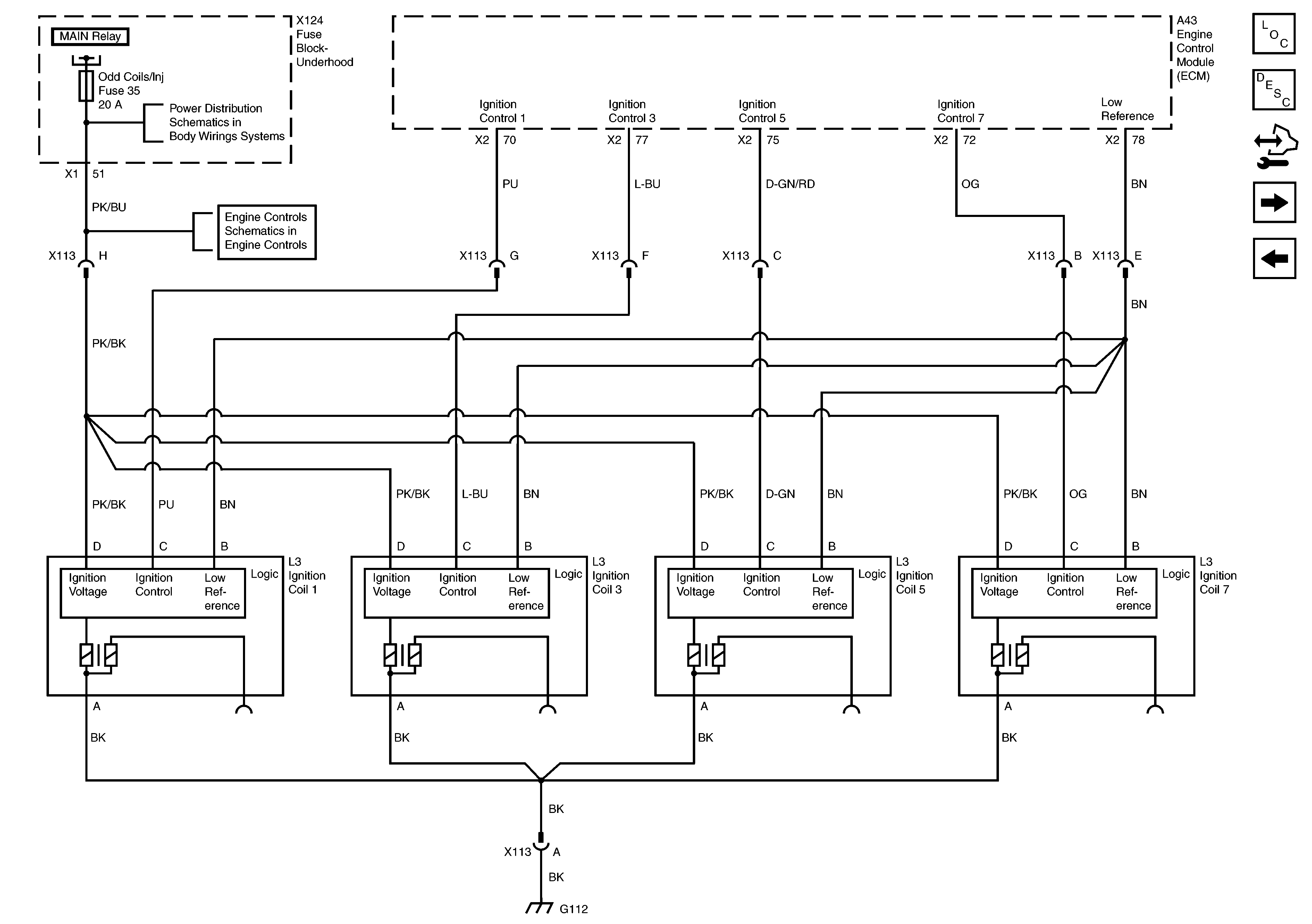
Figure 4:

Odd Ignition Coils


Object Number: 1962329  Size: FS
Master Electrical Component List
Engine Control Module Description
Control Module References
Even Ignition Coils
Fuel Injectors
B+ Bus - 1 of 2
ECM Power, Ground and Serial Data
B+ Bus - 1 of 2
G103, G110, G111 and G112 (6.0L)
Figure 5:

Even Ignition Coils


Object Number: 1962330  Size: FS
Master Electrical Component List
Engine Control Module Description
Control Module References
Crankshaft Position and Knock Sensors
Odd Ignition Coils
G103, G110, G111 and G112 (6.0L)
B+ Bus - 1 of 2
ECM Power, Ground and Serial Data
Figure 6:

Crankshaft Position and Knock Sensors


Object Number: 1962331  Size: FS
Master Electrical Component List
Engine Control Module Description
Control Module References
Heated Oxygen Sensors
Even Ignition Coils
Engine Controls Schematic Icons
Figure 7:

Heated Oxygen Sensors


Object Number: 1962333  Size: FS
Master Electrical Component List
Engine Control Module Description
Control Module References
Camshaft Position Sensor, MAP Sensor, Reverse Lockout Solenoid, Evap Canister Purge Solenoid, Coolant Temp Sensor, MAF Sensor, Oil Level and Temp Sensor and Backup Lamp Switch
Crankshaft Position and Knock Sensors
ECM Power, Ground and Serial Data
Batt Main 1, Courtesy Lights, Instrument/Ctr Display/RFA/DLC, Turn Signal Left and Turn Signal Right Fuses and Window Batt Circuit Breakers
Figure 8:

Camshaft Position Sensor, MAP Sensor, Reverse Lockout Solenoid, Evap Canister Purge Solenoid, Coolant Temp Sensor, MAF Sensor, Oil Level and Temp Sensor and Backup Lamp Switch


Object Number: 1962332  Size: FS
Master Electrical Component List
Engine Control Module Description
Control Module References
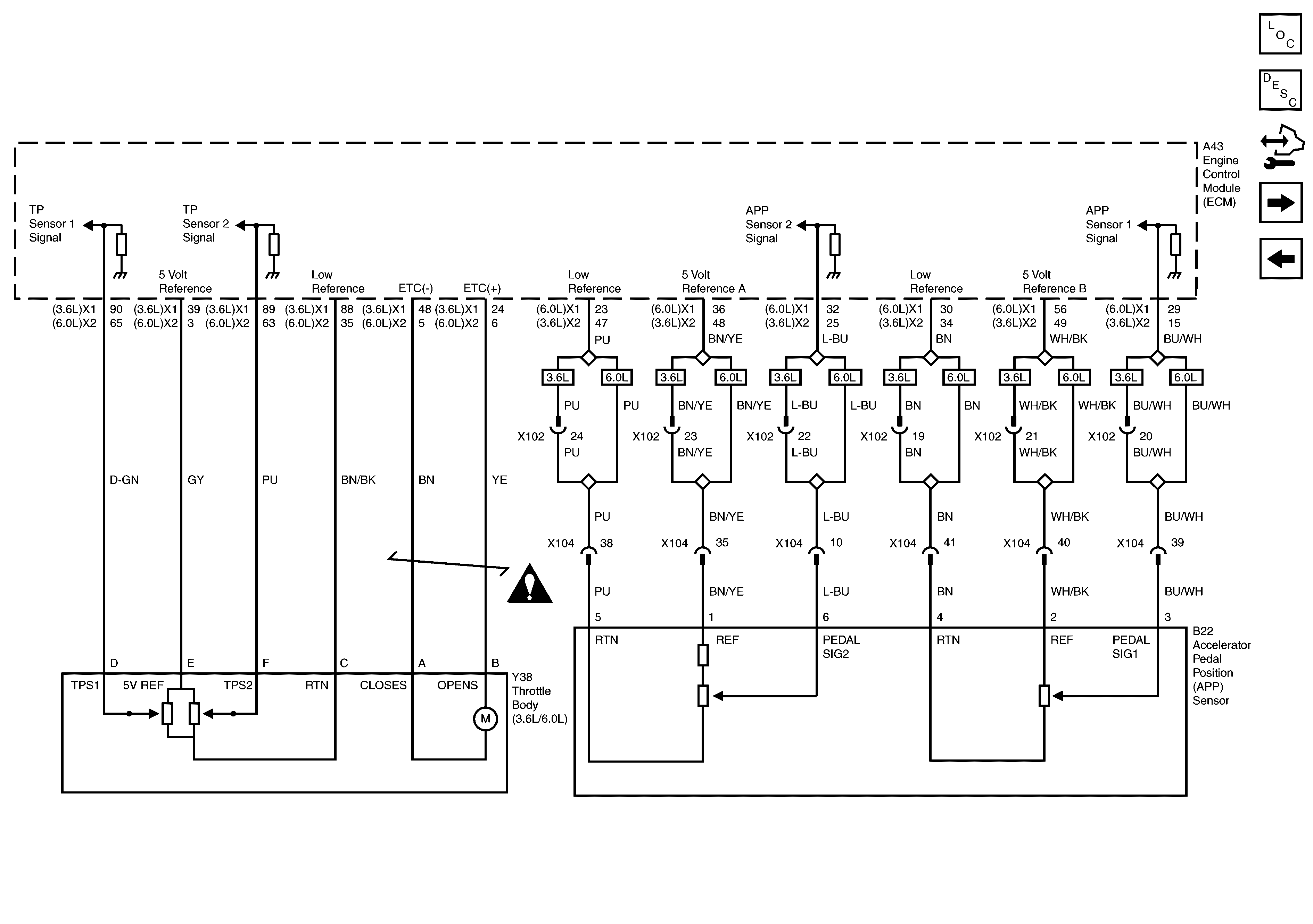
Throttle Body and APP Sensor
Heated Oxygen Sensors
G101 and G102
G103, G110, G111 and G112 (6.0L)
ECM Power, Ground and Serial Data
Heated Oxygen Sensors
B+ Bus - 1 of 2
B+ Bus - 1 of 2
B+ Bus - 1 of 2
B+ Bus - 1 of 2
B+ Bus - 1 of 2
B+ Bus - 1 of 2
B+ Bus - 1 of 2
Figure 9:

Throttle Body and APP Sensor


Object Number: 1962310  Size: FS
Master Electrical Component List
Engine Control Module Description
Control Module References
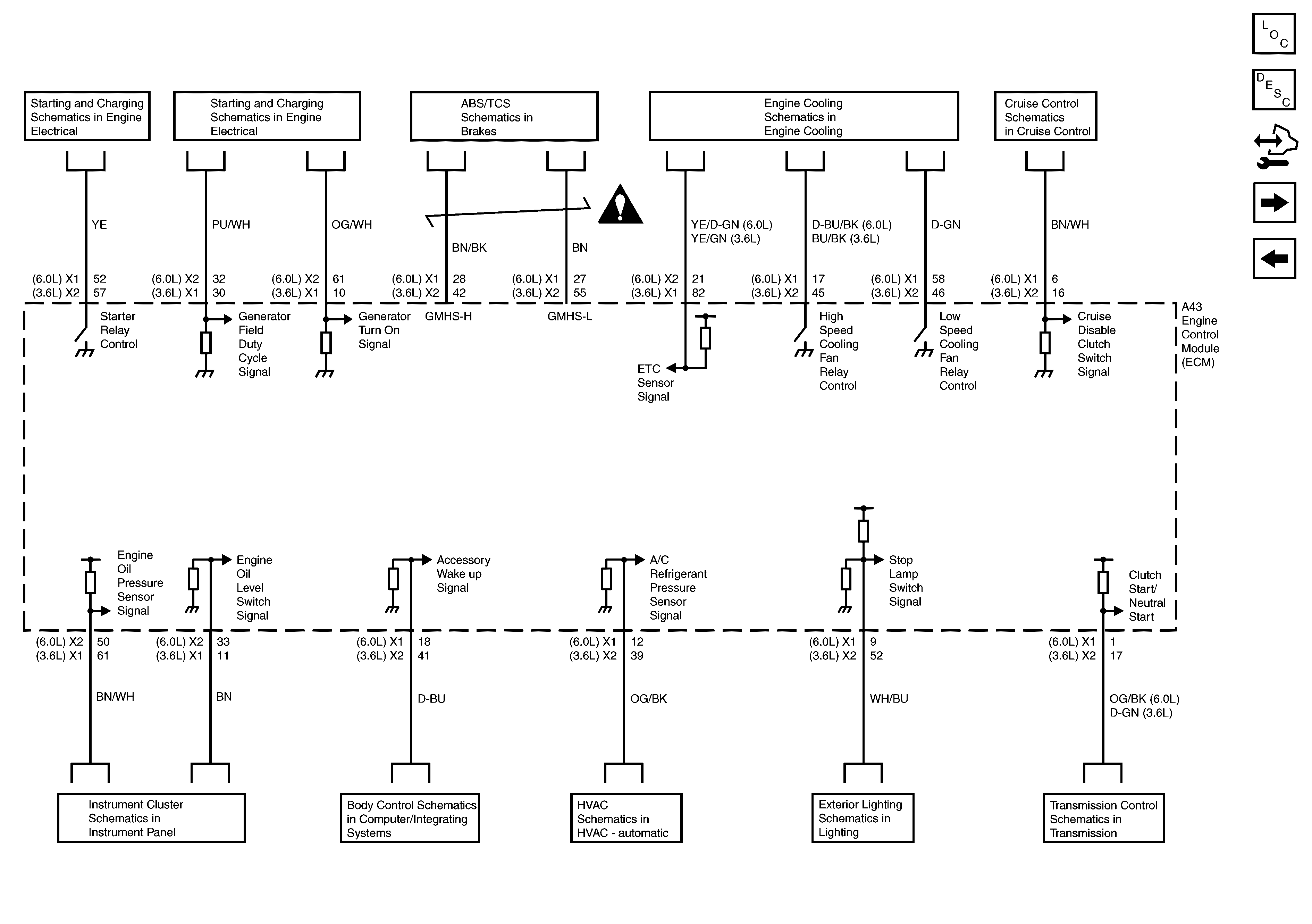
ECM Inputs and Outputs
Camshaft Position Sensor, MAP Sensor, Reverse Lockout Solenoid, Evap Canister Purge Solenoid, Coolant Temp Sensor, MAF Sensor, Oil Level and Temp Sensor and Backup Lamp Switch
Engine Controls Schematic Icons
Figure 10:

ECM Inputs and Outputs


Object Number: 1962300  Size: FS
Master Electrical Component List
Engine Control Module Description
Control Module References
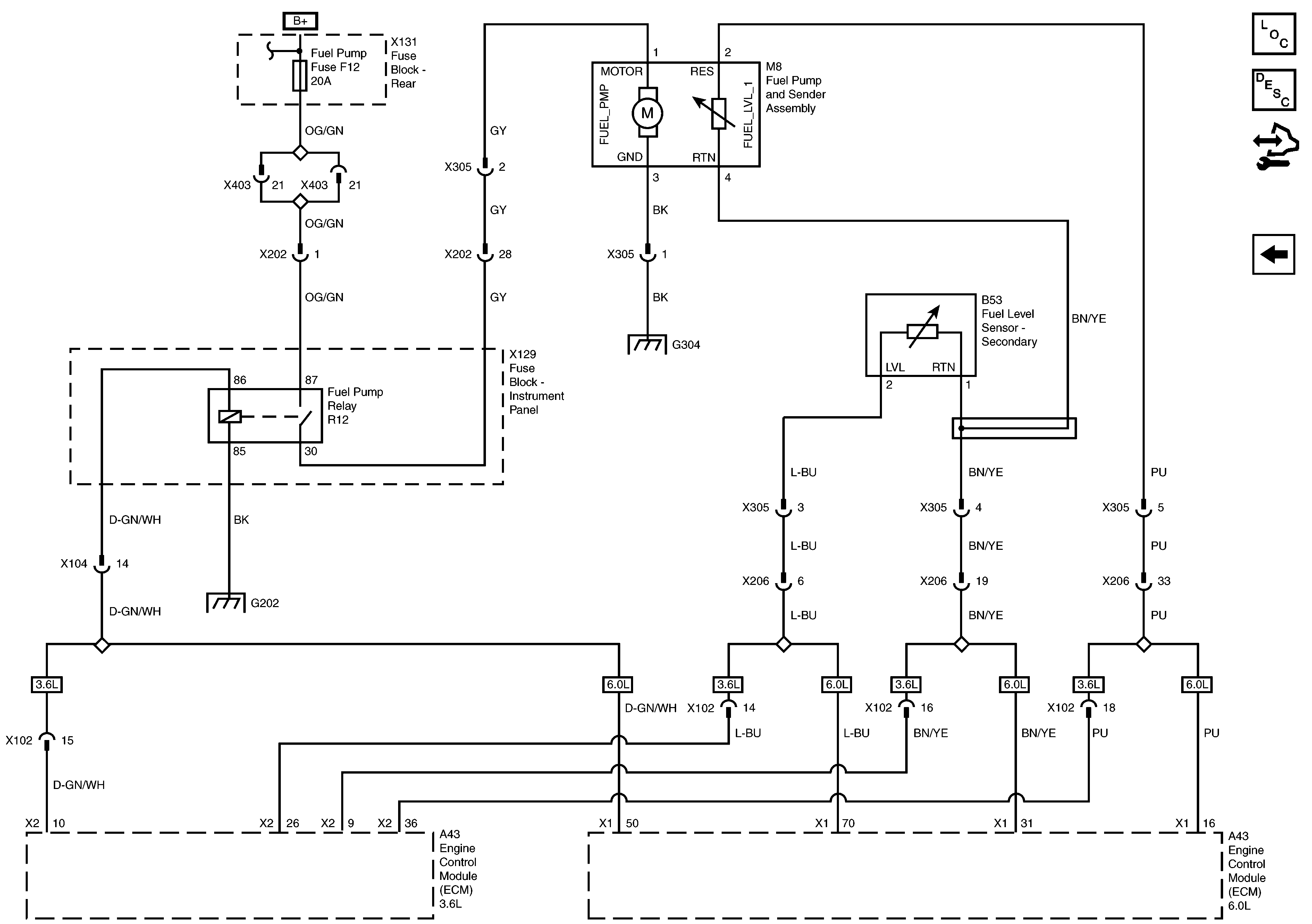
Fuel Pump and Fuel Level Sensor
Throttle Body and APP Sensor
Cruise Control Switch, Automatic Transmission Shift Lever, Multifunction Center Console Switch and Clutch Cruise Switch
Cooling Fans and Relays
Module Power, Ground and Serial Data
Battery, Starter and Ignition Switch, Inputs and Outputs
Battery Current Sensor and Generator, Inputs and Outputs
Instrument Cluster Power, Ground, Serial Data, Inputs and Outputs
HVAC Module, Power, Ground, Serial Data, Inputs and Outputs
Stop Lamps Power and Ground
TCM and Transmission, Power, Ground, Serial Data, Inputs and Outputs
Cruise Control Switch, Automatic Transmission Shift Lever, Multifunction Center Console Switch and Clutch Cruise Switch
Engine Controls Schematic Icons
Figure 11:

Fuel Pump and Fuel Level Sensor


Object Number: 1962298  Size: FS
Master Electrical Component List
Engine Control Module Description
Control Module References
ECM Inputs and Outputs
G303 and G304 - 1 of 2
G202