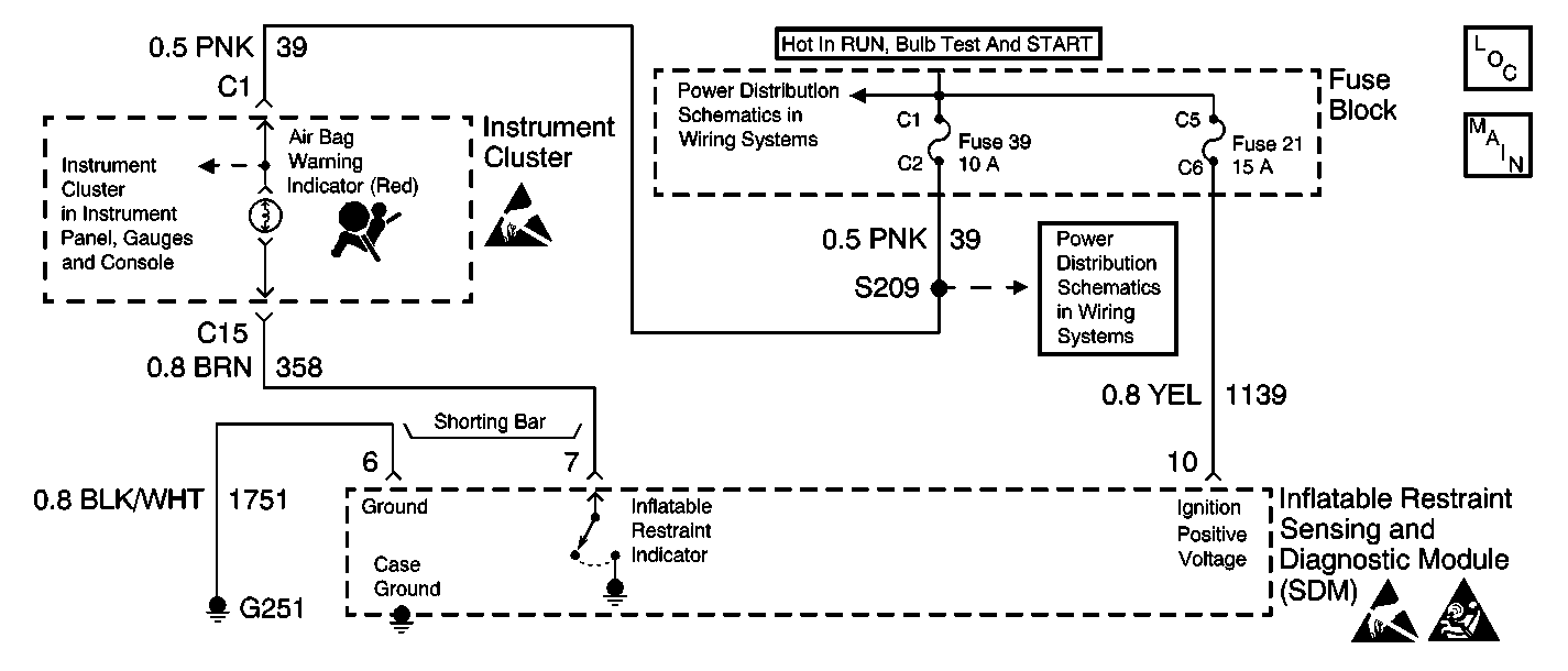
Circuit Description
The ignition switch supplies IGNITION 1 voltage to the inflatable restraint sensing and diagnostic module (SDM) using Fuse 21. The ignition switch also supplies IGNITION 1 voltage to the AIR BAG warning lamp using Fuse 39. The AIR BAG warning lamp is connected to the INFLATABLE RESTRAINT INDICATOR at the SDM. When the ignition switch is first turned to RUN, the SDM responds by flashing the AIR BAG warning lamp seven times. If IGNITION 1 is outside of the normal operating voltage range (8.2 volts-17.1 volts), the AIR BAG warning lamp will come ON solid with no DTC's set.
Diagnostic Aids
In order to disable the shorting bar from the inflatable restraint indicator circuit and the ground circuit inside the inflatable restraint sensing and diagnostic module (SDM) wiring harness connector, the following two conditions must be met:
| • | The SDM wiring harness connector must be properly connected to the SDM. |
| • | The connector position assurance (CPA) must be properly installed in the SDM wiring harness connector. |
When measurements are requested in this table, use the J 39200 DMM with the correct terminal adapter from the J 35616 Connector Test Adapter Kit. When an inspection for proper connection is requested, refer to Testing for Electrical Intermittents in Wiring Systems. When a wire, connector or terminal repair is requested, use the J-38125 Terminal Repair Kit and refer to Wiring Repairs in Wiring Systems.
Test Description
The numbers below refer to the step numbers on the diagnostic table:
-
This step checks to see if sufficient IGNITION voltage is applied to the SDM.
-
This step checks to see if excessive IGNITION voltage is applied to the SDM.
-
This step checks to see if the connector position assurance (CPA) is properly installed.
-
This step determines if the SDM is turning on the AIR BAG warning lamp or if there is a malfunctioning SDM.
-
This step checks to see if the shorting bar is damaged.
-
This step checks to see if there is a short to ground in CKT 358.
-
This step determines if there is a short between the inflatable restraint indicator circuit and the ground circuit or if there is a short to ground in the inflatable restraint indicator circuit.
-
This step checks to see if Fuse 21 is OK. An open Fuse 21 would cause the AIR BAG warning lamp to come on steady.
-
This step checks to see if a short to ground caused Fuse 21 to open.
-
This step checks to see if there is a short to ground in the ignition positive voltage circuit.
-
This step checks to see if the SDM wiring harness connector properly secures to the SDM.
-
This step checks to see if there is an open in the ignition positive voltage circuit.
-
This step determines if there is an open or a high resistance in the B+ feed circuit to the input side of Fuse 21 or if there is a malfunctioning SDM.
Step | Action | Value(s) | Yes | No |
|---|---|---|---|---|
1 | Did you perform the SIR Diagnostic System Check? | -- | ||
Is IGNITION more than the specified value? | 8.2 V | |||
Is IGNITION more than the specified value? | 17.1 V | Go to Diagnostic System Check - Engine Electrical in Engine Electrical | ||
Is the CPA properly installed? | -- | |||
5 | Properly install the CPA. Did you complete the repair? | -- | -- | |
Does the AIR BAG warning lamp come ON steady? | -- | |||
Is the shorting bar damaged or corroded? | -- | |||
8 | Replace the SDM wiring harness connector. Refer to Connector Repairs in Wiring Systems. Did you complete the repair? | -- | -- | |
Is the measured resistance less than the specified value? | OL | |||
Is the measured resistance less than the specified value? | OL | |||
11 |
Did you complete the repair? | -- | -- | |
12 |
Did you complete the repair? | -- | -- | |
13 | Replace the instrument cluster. Refer to Instrument Cluster Replacement in Instrument Panel, Gages and Console. Is the repair complete? | -- | -- | |
Is Fuse 21 good? | -- | |||
Is Fuse 21 good? | -- | |||
Is the measured resistance less than the specified value? | OL | |||
17 |
Did you complete the repair? | -- | -- | |
18 | Install Fuse 21. Did you complete the repair? | -- | -- | |
Inspect the SDM wiring harness connector. Refer to Inflatable Restraint Sensing and Diagnostic Module Replacement . Is the connector secure? | -- | |||
20 |
Did you complete the repair? | -- | -- | |
21 |
Is the SDM wiring harness connector damaged or corroded? | -- | ||
22 | Replace the SDM wiring harness connector. Refer to Connector Repairs in Wiring Systems. Did you complete the repair? | -- | -- | |
23 | Inspect the SDM terminals for damage or corrosion. Are any terminals damaged or corroded? | -- | ||
24 | Replace the SDM. Refer to Inflatable Restraint Sensing and Diagnostic Module Replacement . Is the repair complete? | -- | -- | |
Use the J 39200 to measure the resistance between the output side of Fuse 21 and the ignition positive voltage circuit at the SDM wiring harness connector. Is the measured resistance within the specified value? | 0-2 ohms | |||
26 |
Did you complete the repair? | -- | -- | |
Is the measured voltage within the specified value? | B+ | Go to Power Distribution Schematics in Wiring Systems | ||
28 |
Did you complete the action? | -- | -- |
