For 1990-2009 cars only
Removal Procedure
- Remove the engine cover. Refer to Engine Cover Replacement in Interior Trim.
- Remove the air cleaner. Refer to Air Cleaner Replacement in Engine Controls.
- Loosen the charged air cooler outlet duct to intake hose clamp.
- Remove the charged air cooler outlet duct from the intake.
- Remove the fuel injection control module. Refer to Fuel Injector Control Module Replacement in Engine Controls.
- Remove the exhaust gas recirculation (EGR) cooler tube. Refer to Exhaust Gas Recirculation Valve Cooler Replacement in Engine Controls.
- Remove the fuel injectors. Refer to Fuel Injector Replacement .
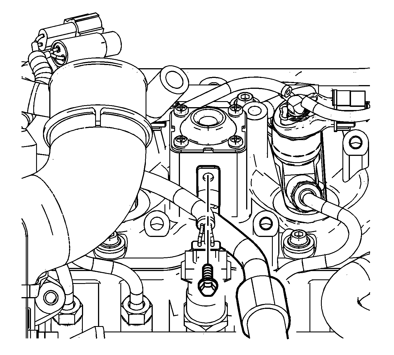
- Remove the heater outlet hose bolt and nut.
- Position the heater outlet hose out of the way.
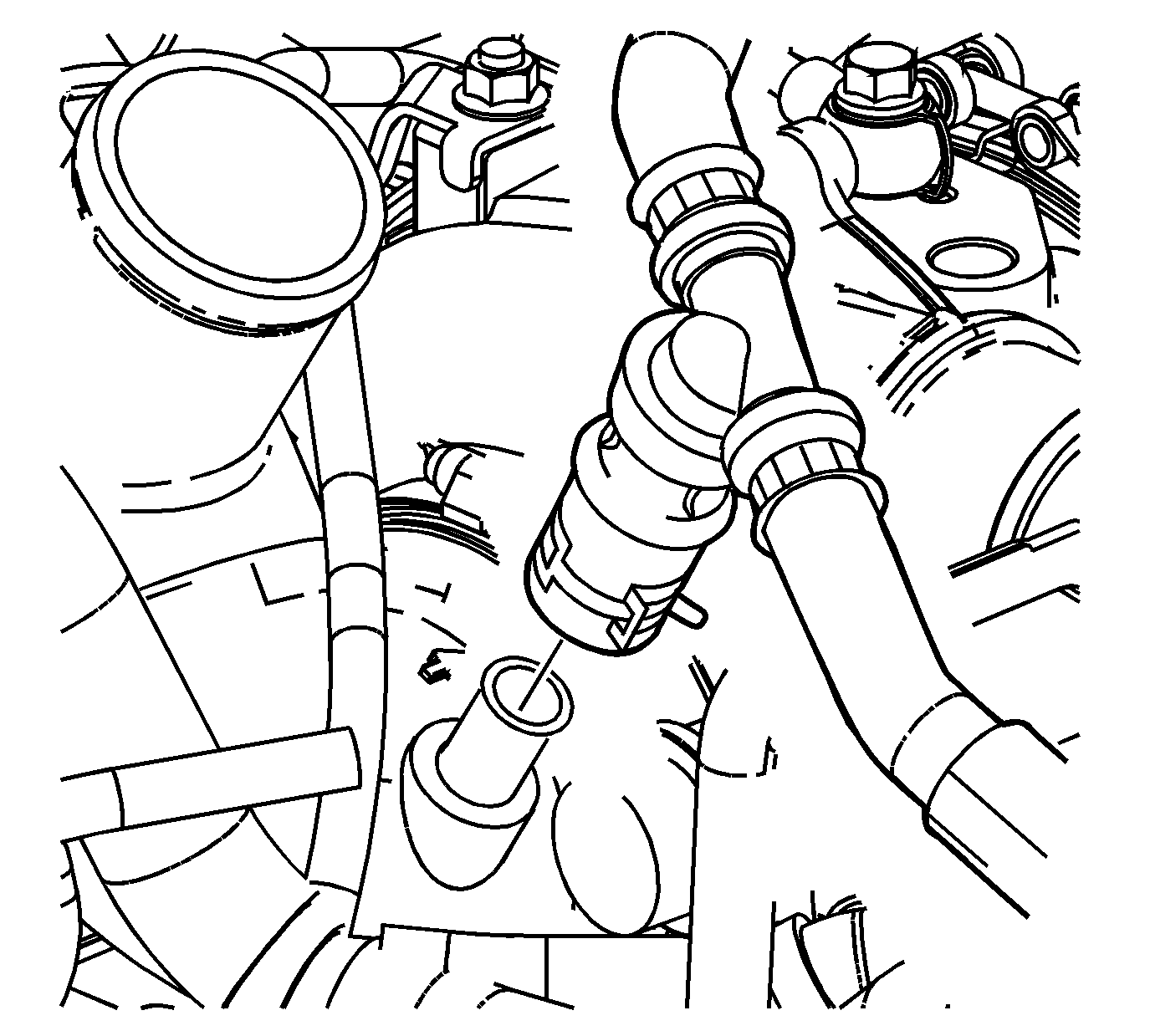
- Reposition the right positive crankcase ventilation (PCV) hose clamp at the resonator tee.
- Remove the PCV hose from the tee.
- Remove the right PCV pipe bolt.
- Remove the right PCV pipe.
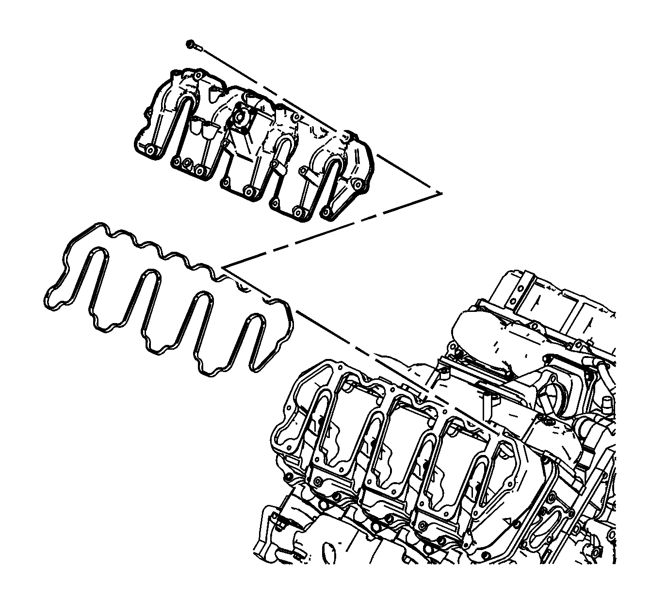
- Remove the upper valve rocker arm cover bolts.
- Remove the upper valve rocker arm cover.
- Remove and discard the upper valve rocker arm cover gasket.
- If required, clean and inspect the upper valve rocker arm cover. Refer to Valve Rocker Arm Cover Cleaning and Inspection - Upper .
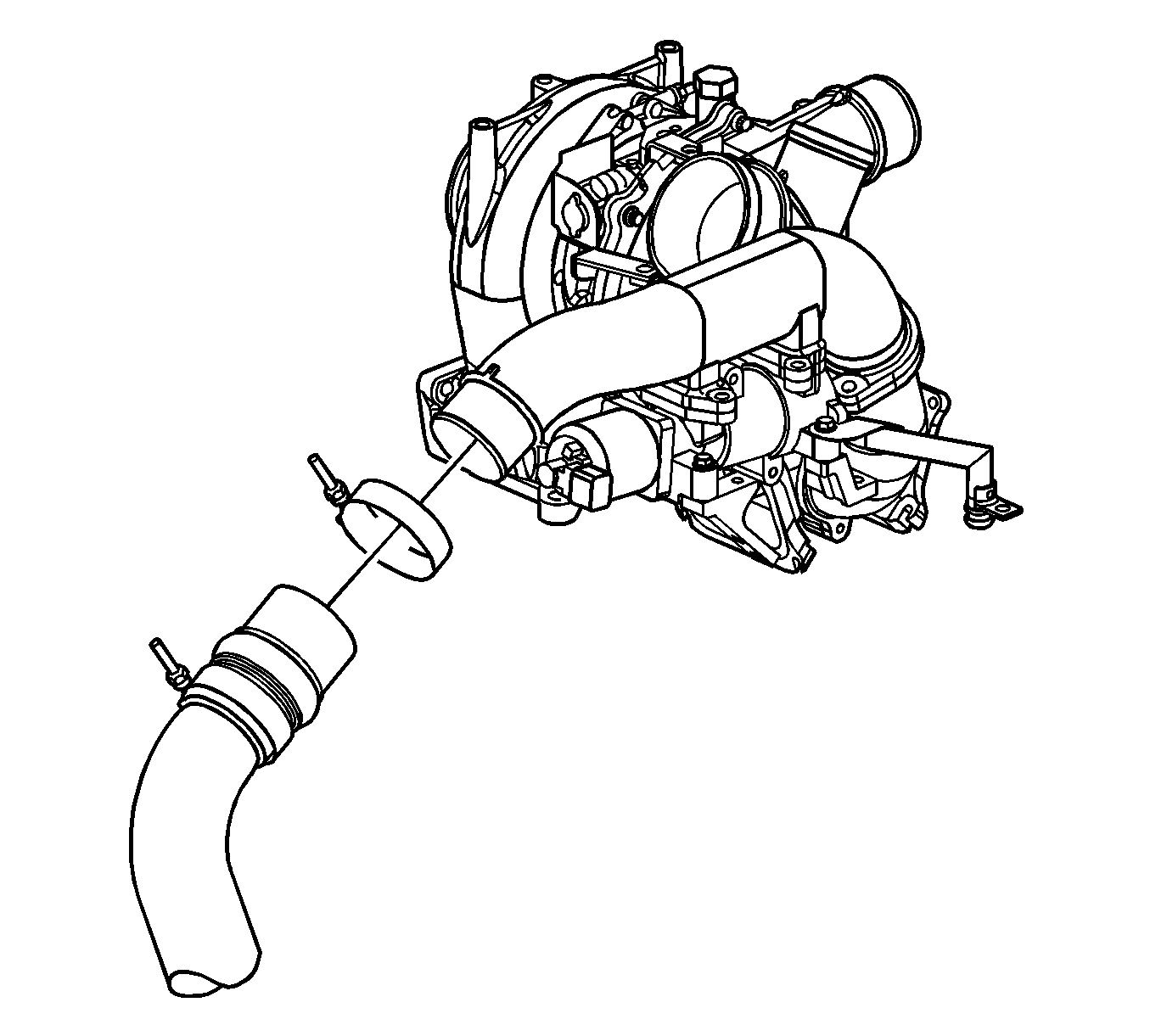
Important: After removing the air cleaner outlet duct, cover the turbocharger opening with tape to prevent entry of objects.
Important: Do not use a screwdriver or other tool to pry the hose loose. The hose can be torn or damaged. Loosen the hose by twisting.
Installation Procedure
- Inspect the upper valve rocker arm cover gasket for damage. If the upper valve rocker arm cover gasket is not damaged, reuse the gasket.
- Install the upper valve rocker arm cover gasket.
- Install the upper valve rocker arm cover.
- Install the upper valve rocker arm cover bolts.
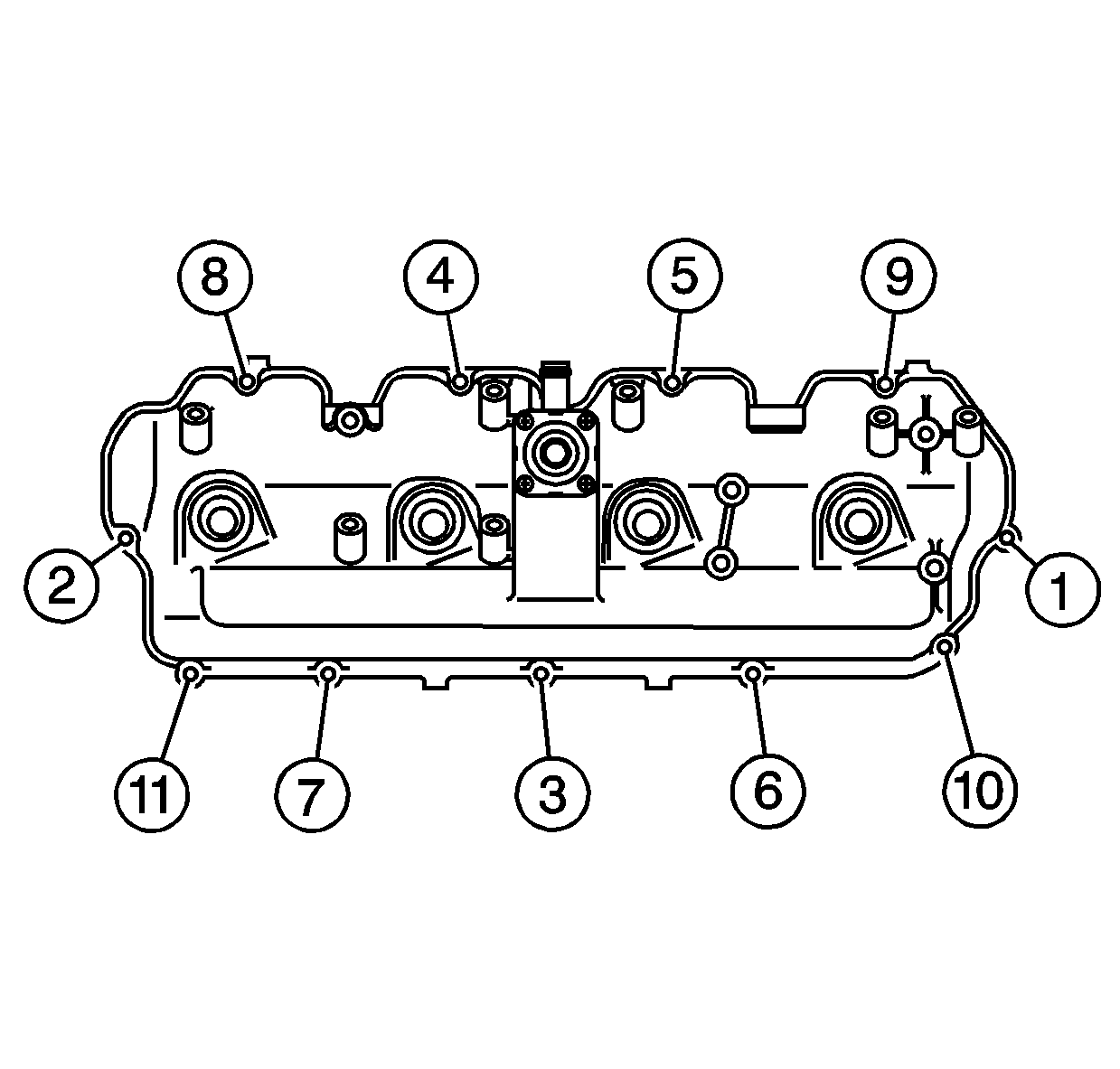
- Tighten the upper valve rocker arm cover bolts in the sequence shown.
- Install the fuel injectors. Refer to Fuel Injector Replacement .
- Install the right PCV pipe.
- Install the right PCV pipe bolt.
- Install the PCV hose to the tee.
- Position the right PCV hose clamp at the resonator tee.
- Position the heater outlet hose.
- Install the heater hose bracket bolt and nut.
- Install the EGR cooler tube. Refer to Exhaust Gas Recirculation Valve Cooler Replacement in Engine Controls.
- Install the fuel injection control module. Refer to Fuel Injector Control Module Replacement in Engine Controls.
- Install the charged air cooler outlet duct to the intake.
- Tighten the charged air cooler outlet duct to intake hose clamp.
- Install the air cleaner. Refer to Air Cleaner Replacement in Engine Controls.
- Install the engine cover. Refer to Engine Cover Replacement in Interior Trim.
Notice: Refer to Fastener Notice in the Preface section.
Tighten
Tighten the bolts to 8 N·m (71 lb in).
Tighten
Tighten the bolt to 18 N·m (13 lb ft).
Tighten
| • | Tighten the nut to 9 N·m (80 lb in). |
| • | Tighten the bolt to 21 N·m (15 lb ft). |
Important: Lubricate the end of the duct prior to installation.
Tighten
Tighten the clamp to 6 N·m (53 lb in).
