Tools Required
| • | J 3289-20 Holding Fixture |
| • | J 8092 Driver Handle |
| • | J 8614-01 Flange and Puller Holding Tool |
| • | J 37668-A Output Shaft Seal Installer |
| • | J 45239 Needle Bearing Installer |
| • | J 45759 Assembly Fixture |
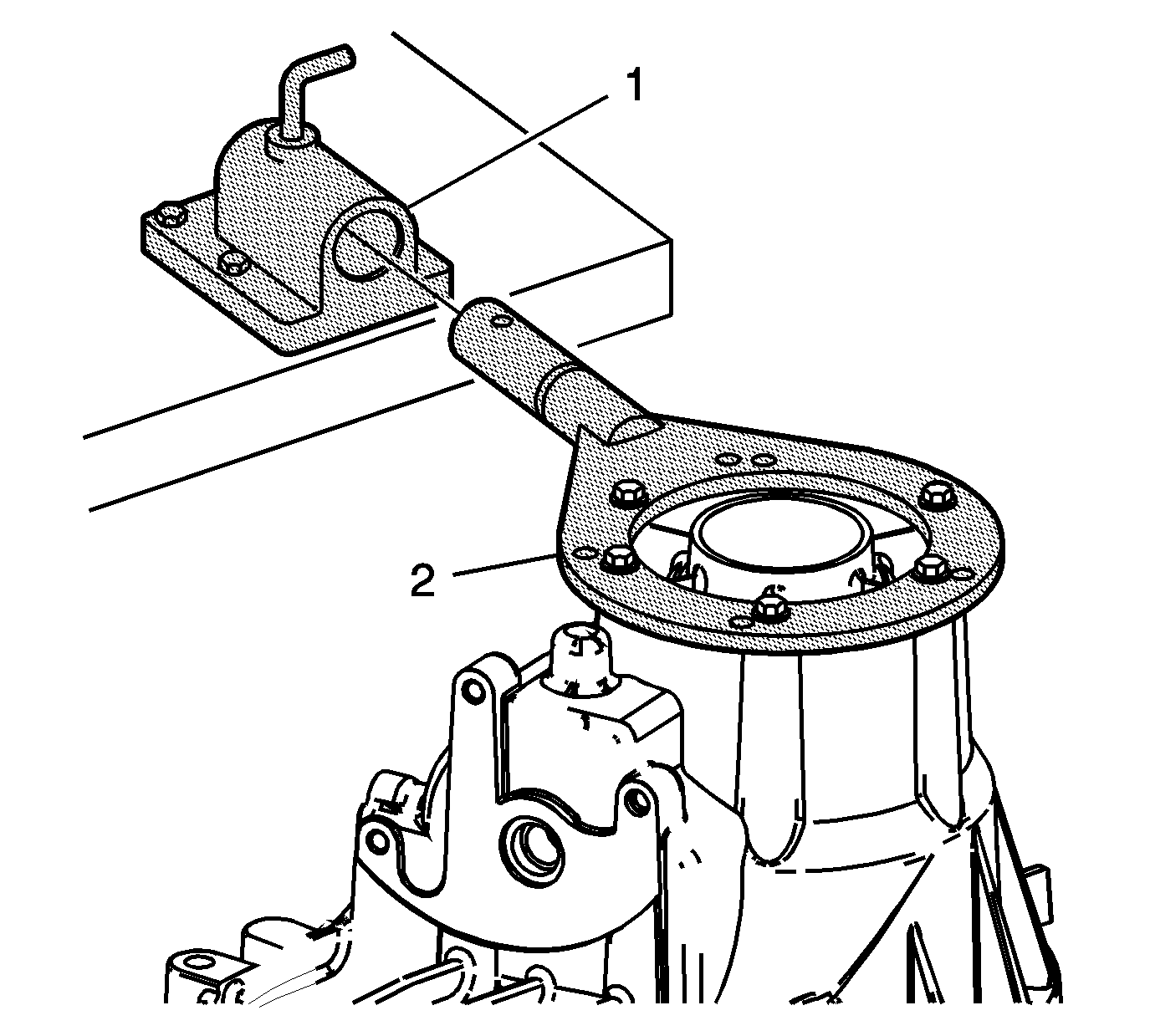
- Attach the J 45759 (2) to the front transfer case using 4 suitable bolts. All of the transfer case assembly procedures can be performed with the case mounted to the J 45759 (2).
- Install the J 45759 (2) into the J 3289-20 (1) and secure with the pivot pin.
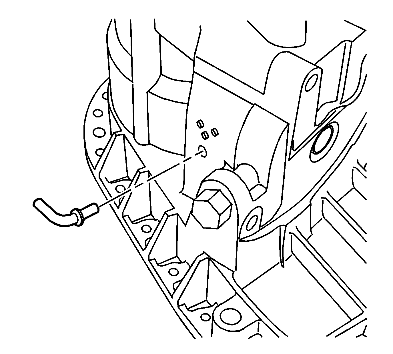
- Apply a small amount of retaining compound GM P/N 12377901 (Canadian P/N 10953504), or equivalent, to the vent tube, if previously removed.
- Install the vent tube elbow, if damaged.
- Wipe any excess retaining compound from inside the front case half.
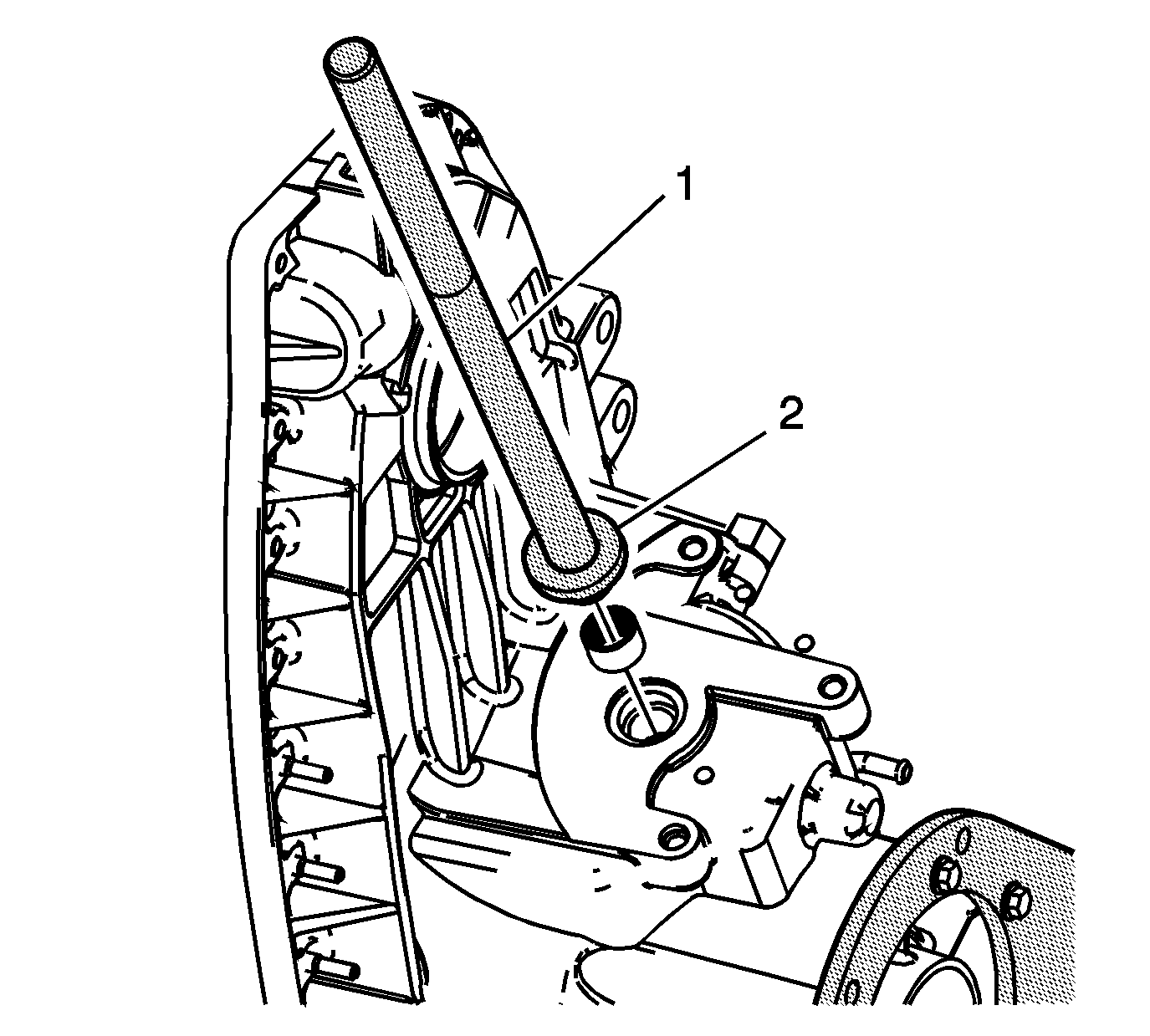
- Using the J 8092 (1) and the J 45239 (2), install the sector bearing into the front case half to bottom. The seal side of the bearing faces outward.
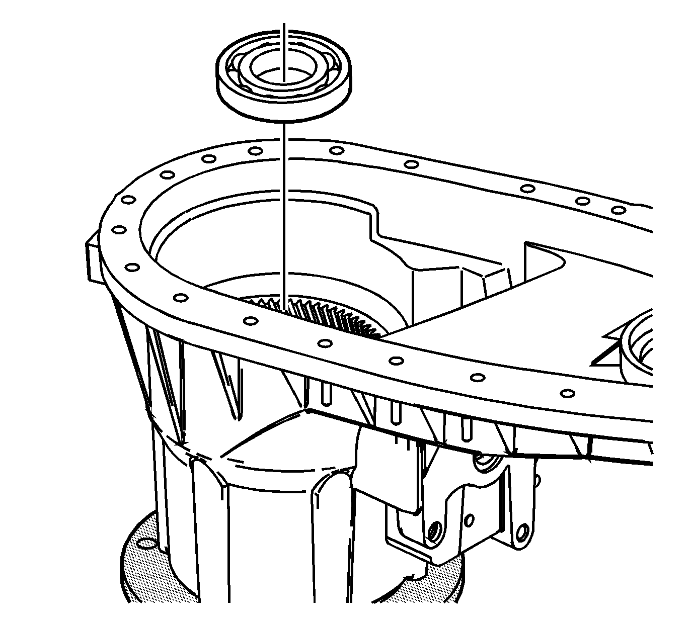
- Using a suitable adapter, install the input gear bearing into the front case half.
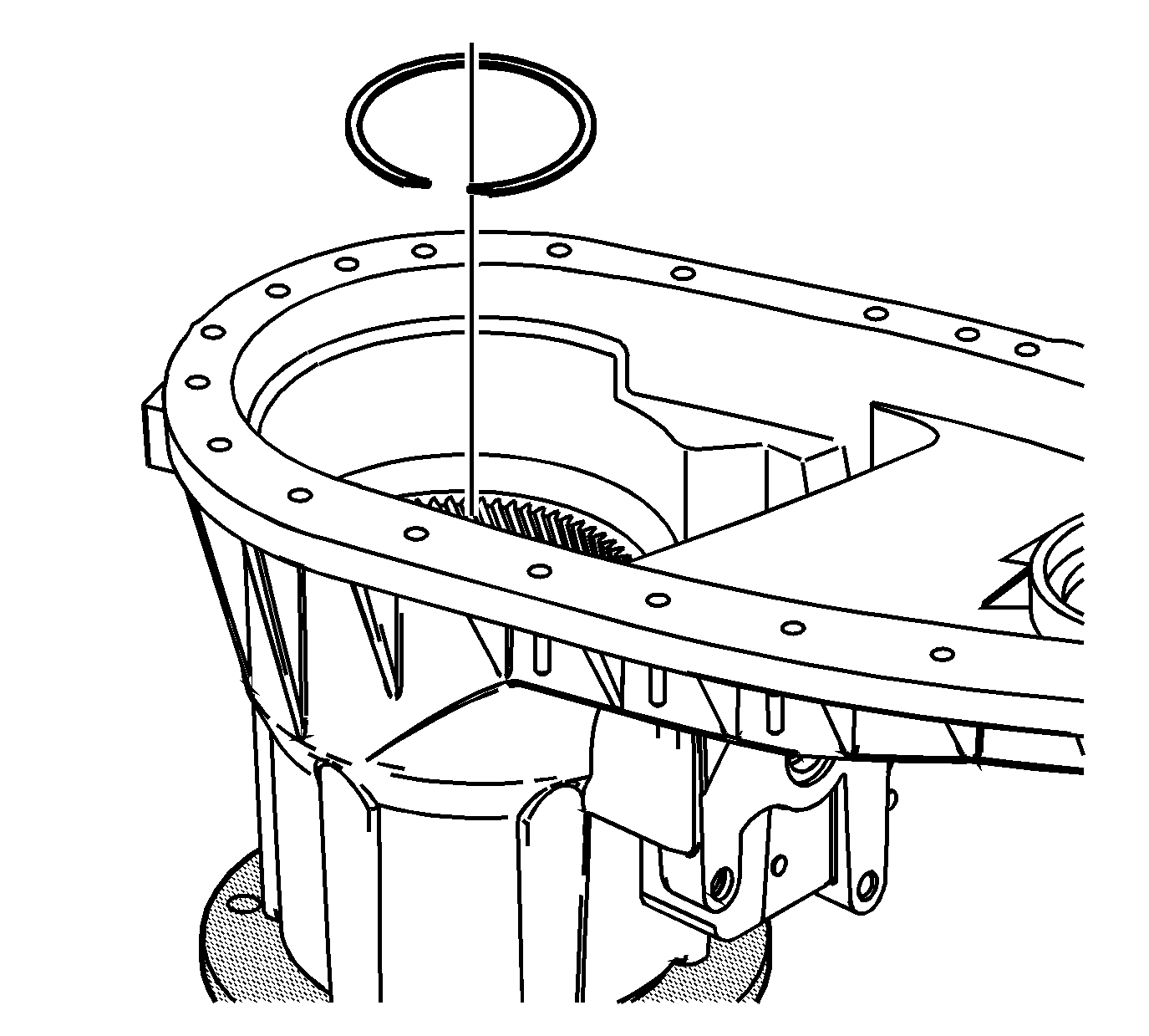
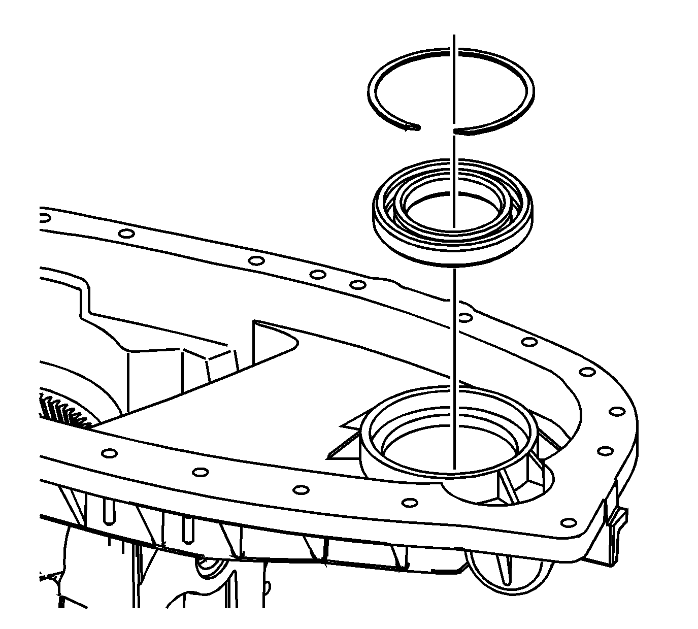
- Install the input gear bearing outer retaining ring.
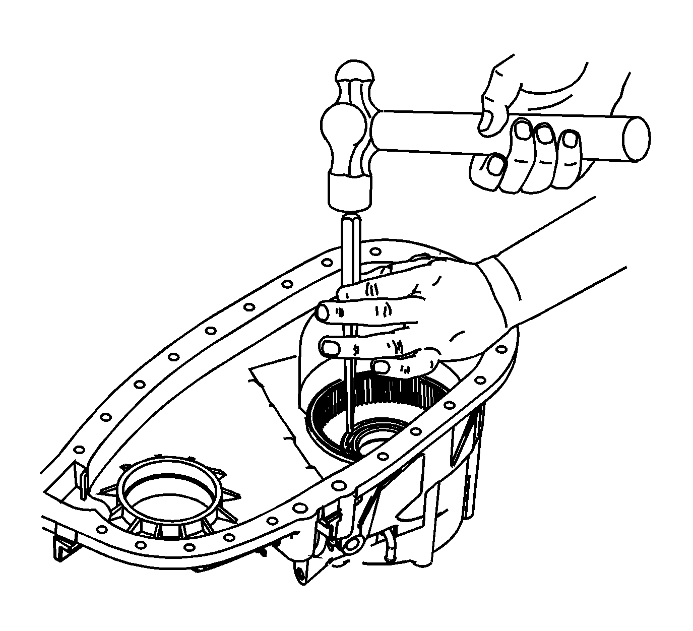
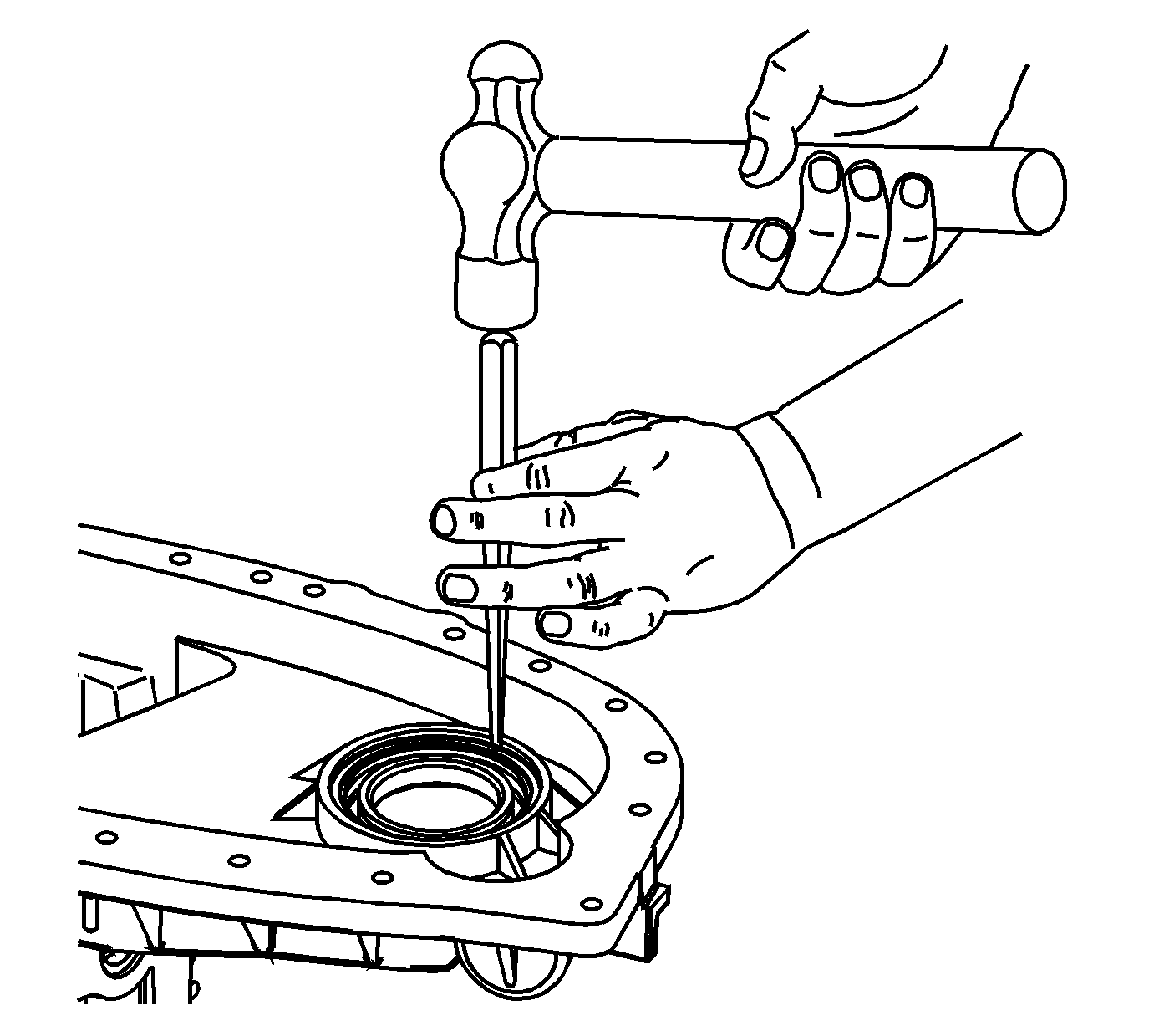
- Using a brass drift, seat the input gear bearing outer retaining ring.
- Using a suitable adapter, install the front output shaft bearing into the front case half.
- Install the front output shaft bearing outer retaining ring.
- Using a brass drift, seat the front output shaft bearing outer retaining ring.
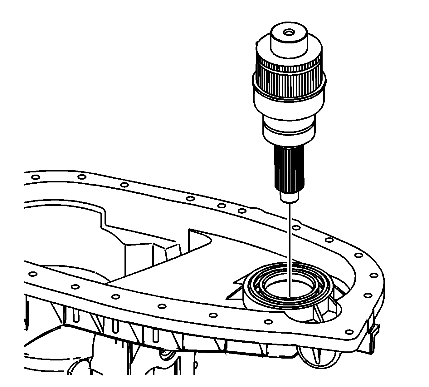
- Install the front output shaft.
- Using a suitable adapter, install the input gear needle bearing into the input gear.
- Install the input gear rear thrust washer (5).
- Install the input gear (4) in the planetary carrier.
- Ensure the input gear turns freely. If the input gear does not turn freely, inspect for debris.
- Install the input gear front thrust washer (3).
- Install the planetary carrier lock plate (2).
- Install the planetary carrier lock plate retaining ring (1).
- Install the high/low planetary assembly.
- Install the front output shaft bearing inner retaining ring.
- Install the input gear bearing inner retaining ring.
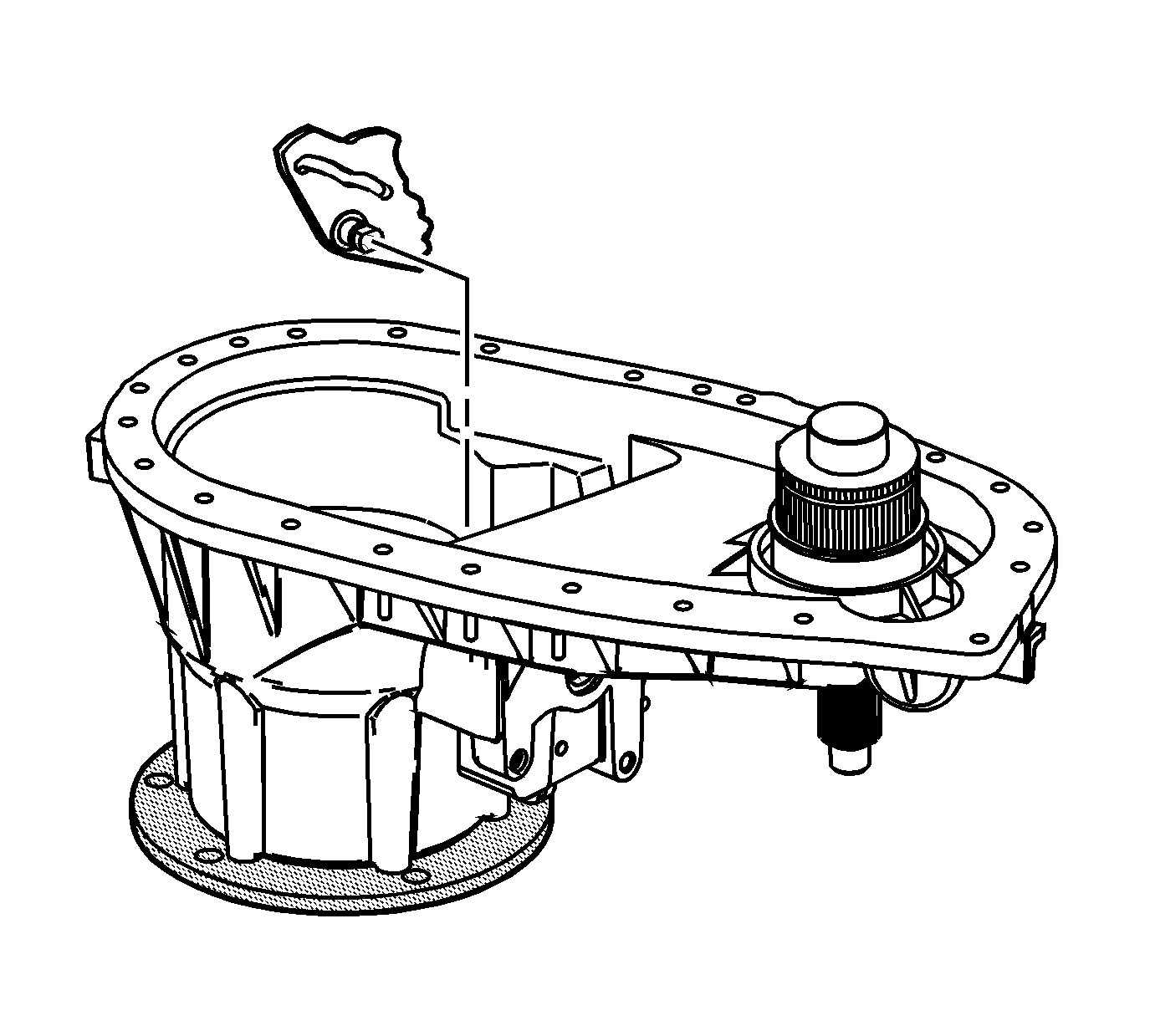
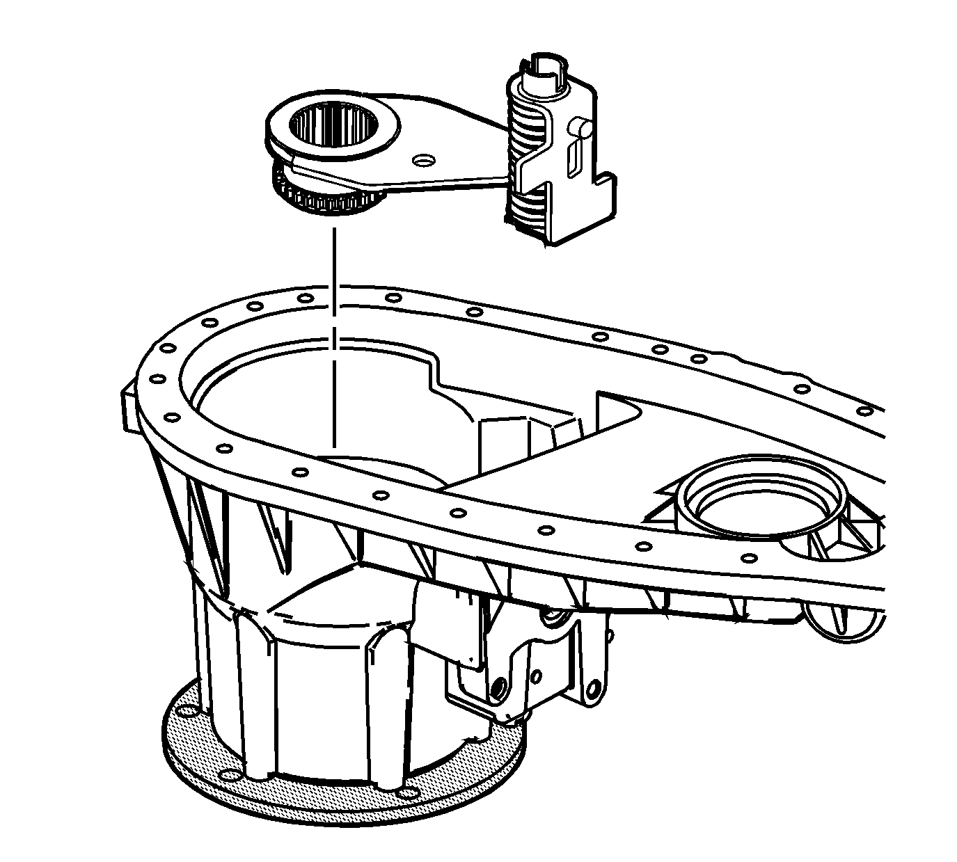
- Install the sector assembly, aligning the detents with the shift detent plunger bore.
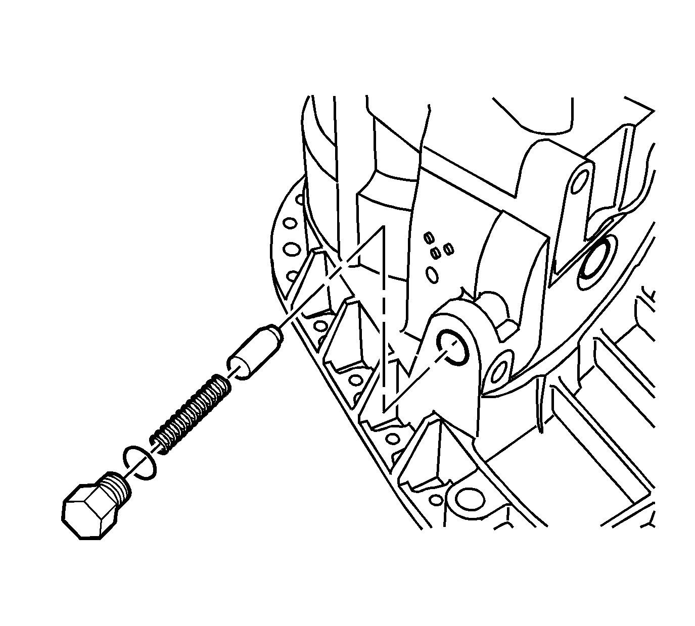
- Install a new O-ring seal on the shift detent spring bolt.
- Install the shift detent plunger, spring, and bolt.
- Install the shift fork pads to the high/low shift fork.
- Install the high/low range sleeve on the high/low shift fork.
- Install the high/low range sleeve with the shift fork to the planetary carrier.
- Position the shift fork pin in the sector range slot.
- Mount the mainshaft (1) in a soft-jaw vise with the input end up.
- Install the drive sprocket hub (2) on the mainshaft (1).
- Install the synchronizer hub (3) on the mainshaft (1).
- Install the synchronizer hub retaining ring (4).
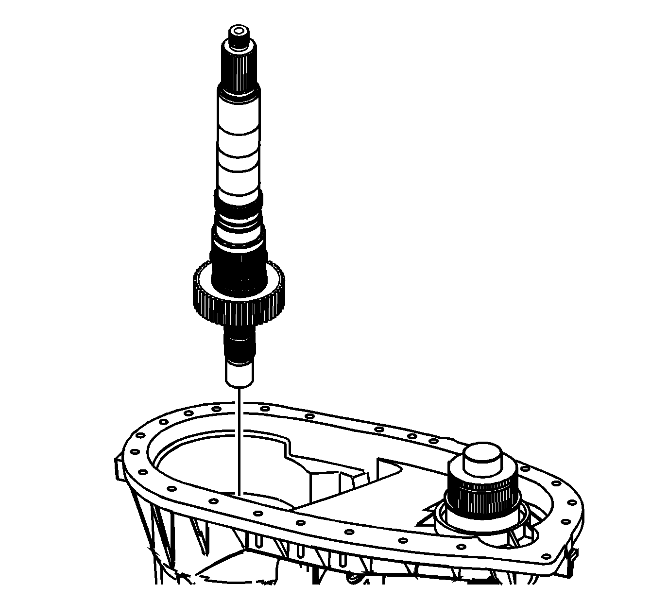
- Install the mainshaft assembly in the front case half.
- Install the pads to the shift fork.
- Install the synchronizer sleeve on the 2/4 wheel drive mode shift fork.
- Install the shift rail and synchronizer sleeve, sliding the shaft through the high/low shift fork and into the front case half bore.
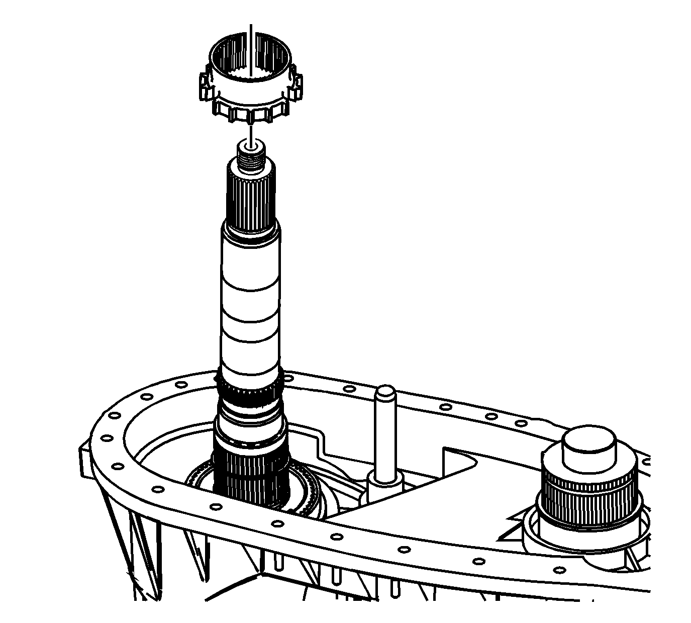
- Install the 2/4 wheel drive synchronizer gear.
- Install the drive chain to the drive sprocket and the driven sprocket.
- Install the drive chain and sprockets to the front output shaft and the mainshaft assembly.
- Install the drive sprocket retaining ring (1).
- Install the driven sprocket retaining ring (2).
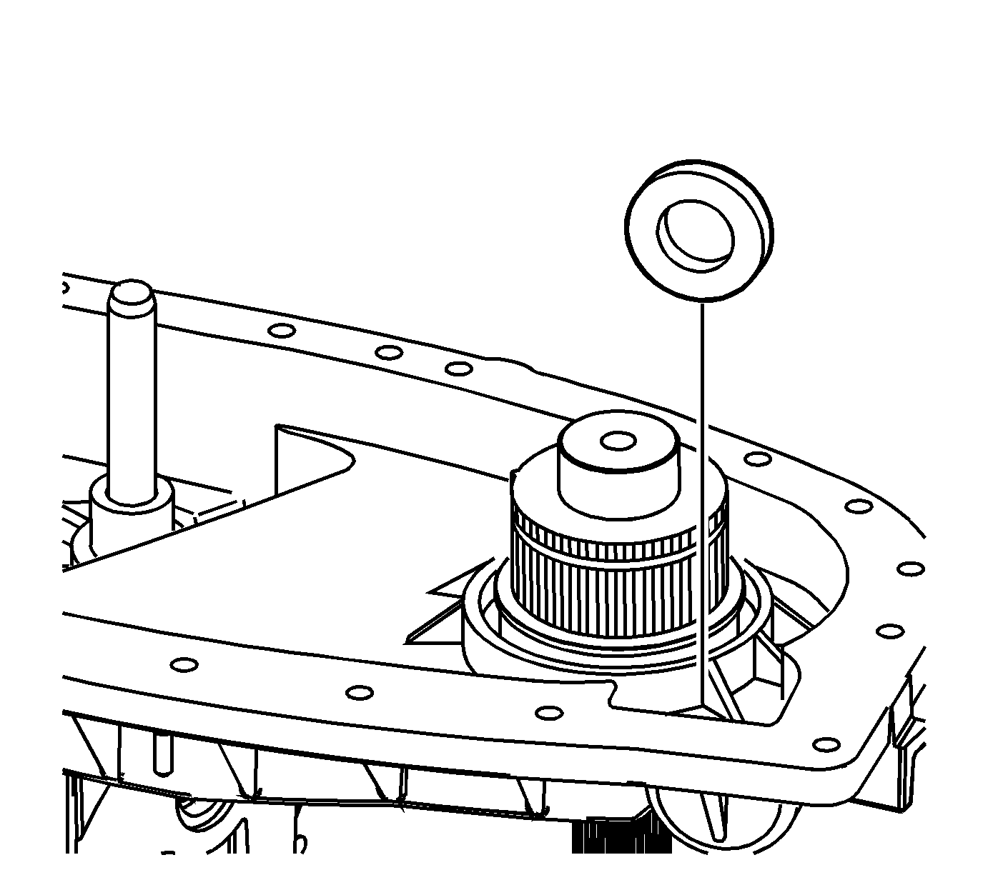
- Install the magnet.
- Install the shift fork shaft spring on the shift shaft.
- Install the locating pins in the front case, if necessary.
- Using a suitable adapter, install the front output needle bearing into the rear case half.
- Using a suitable adapter, install the rear output bearing into the rear case half.
- Install the rear output bearing outer retaining ring.
- Install the oil pump suction pipe and screen into the rear case half.
- Press the upper portion of the hose/pipe assembly into the rear case half to secure.
- Apply a 2 mm (0.078 in) bead of sealer GM P/N 12345739 (Canadian P/N 10953541), or equivalent, to the front case half.
- Install the rear case half to the front case half.
- Install the 3 longer case half bolts in the locations marked during disassembly.
- Install the remaining case half bolts.
- Install the rear output bearing inner retaining ring.
- Lightly lubricate the O-ring seal with clean manual transmission fluid.
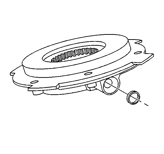
- Install the O-ring seal into the oil pump assembly.
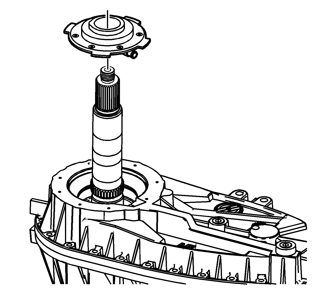
- Install the oil pump assembly over the mainshaft.
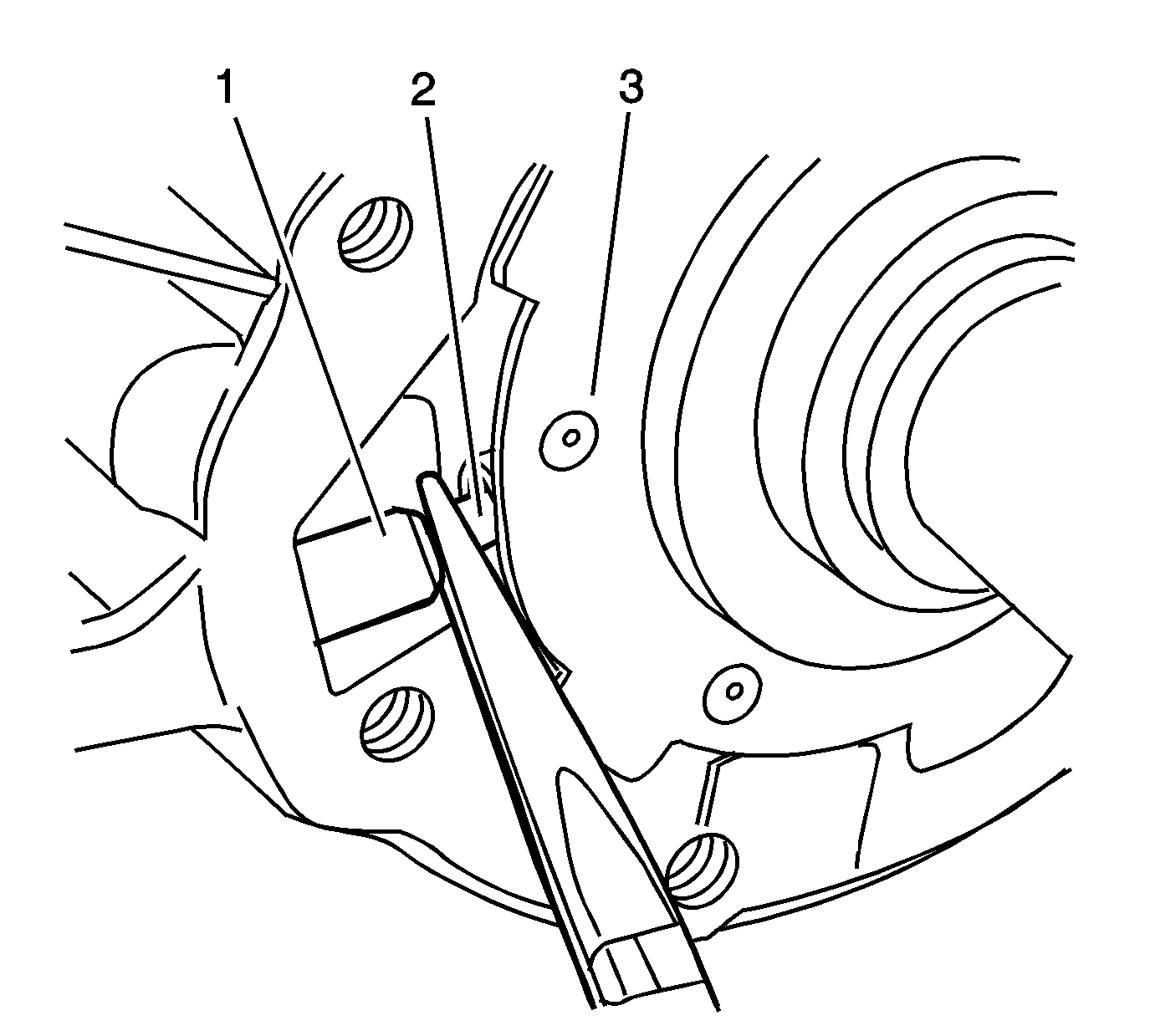
- Using a pair of needle nose pliers, insert the upper connection tube (2) into the oil pump assembly (3).
- Apply a 2 mm (0.078 in) bead of sealer GM P/N 12345749 (Canadian P/N 10953541), or equivalent, to rear case half.
- Using a suitable adapter, install the rear needle bearing into the retainer assembly.
- Install the retainer assembly.
- Install the retainer assembly bolts.
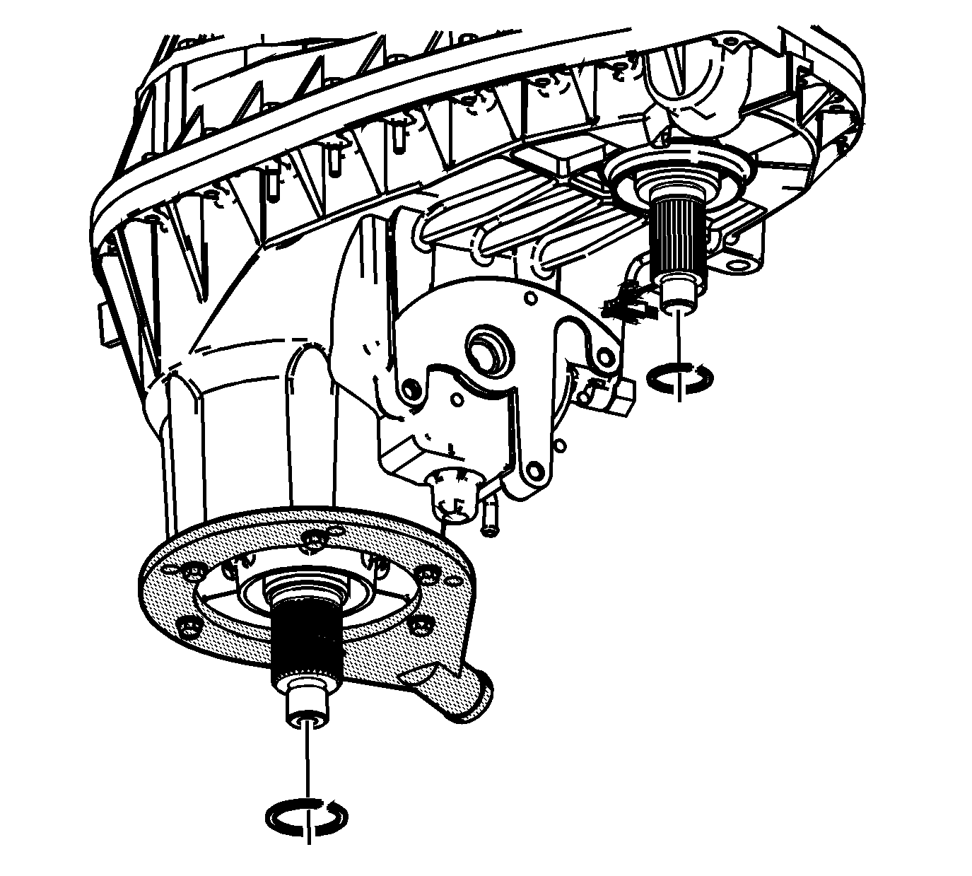
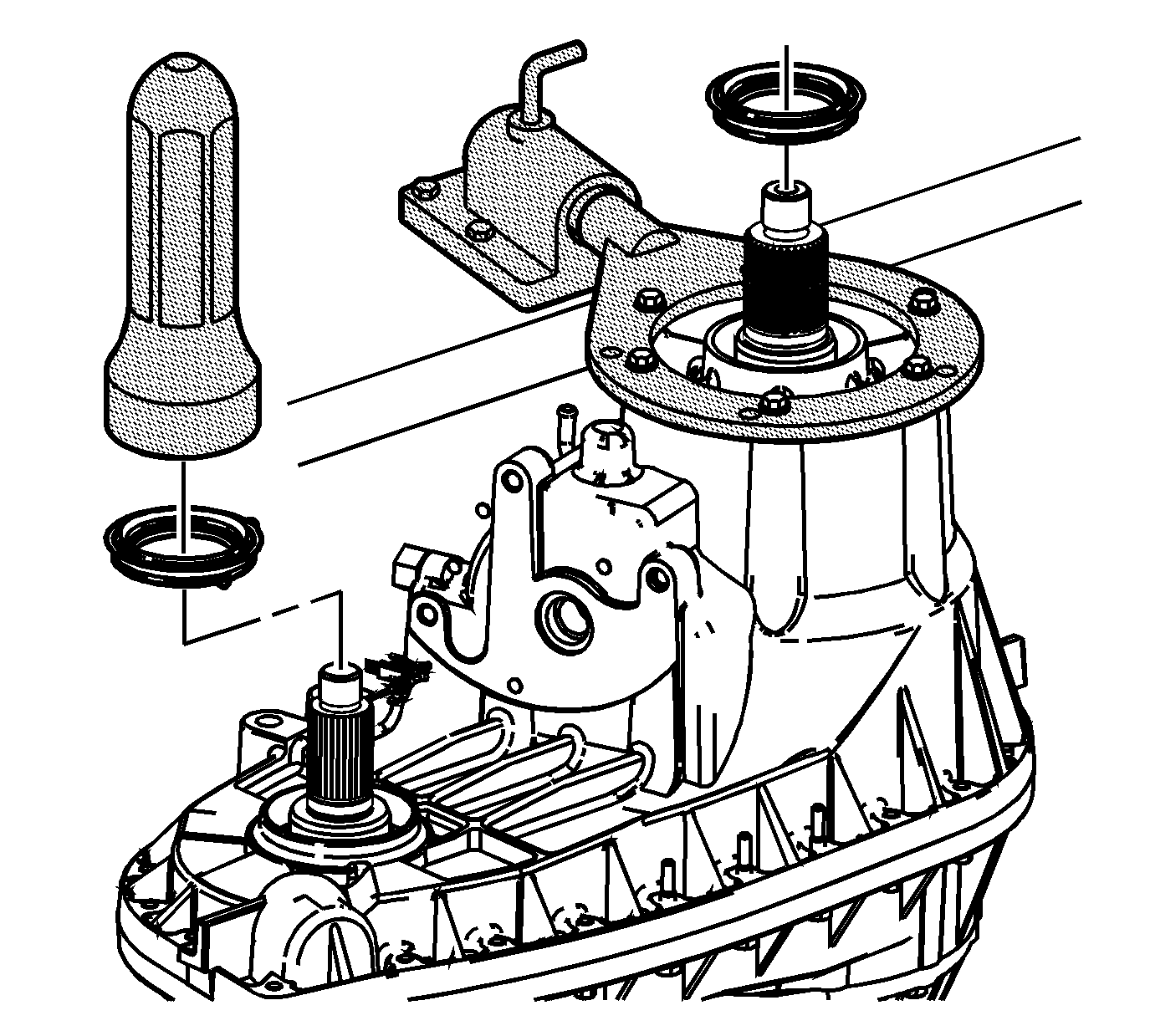
- Using the J 37668-A , install the rear output seal to the transfer case.
- Install the rear output flange.
- Install the J 8614-01 to the rear output flange for support.
- Install the rear output flange nut.
- Rotate the transfer case 180 degrees.
- Using the J 37668-A , install the input and front output seals in the transfer case.
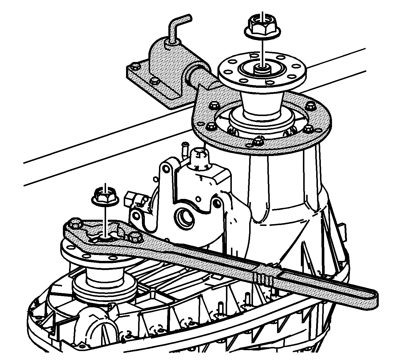
- Install the front output flange and input flange.
- Install the J 8614-01 to the front output flange for support.
- Install the front output flange nut.
- Install the J 8614-01 to the input flange for support.
- Install the input flange nut.
- Install the actuator insulator gasket on the encoder motor.
- Install the actuator encoder motor to the transfer case. Rotate the sector assembly shaft to align to the encoder motor.
- Install the mounting bolts for the actuator encoder motor.
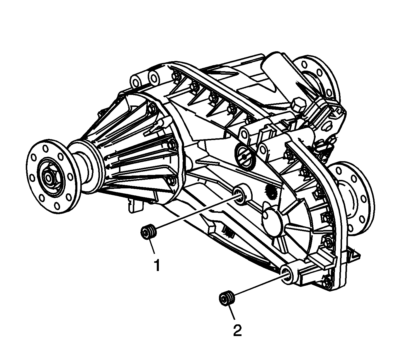
- Apply pipe sealant GM P/N 12346004 (Canadian P/N 10953480), or equivalent, to the drain plug threads.
- Install the drain plug (2).
- Apply pipe sealant GM P/N 12346004 (Canadian P/N 10953480), or equivalent, to the fill plug threads.
- Install the fill plug (1).
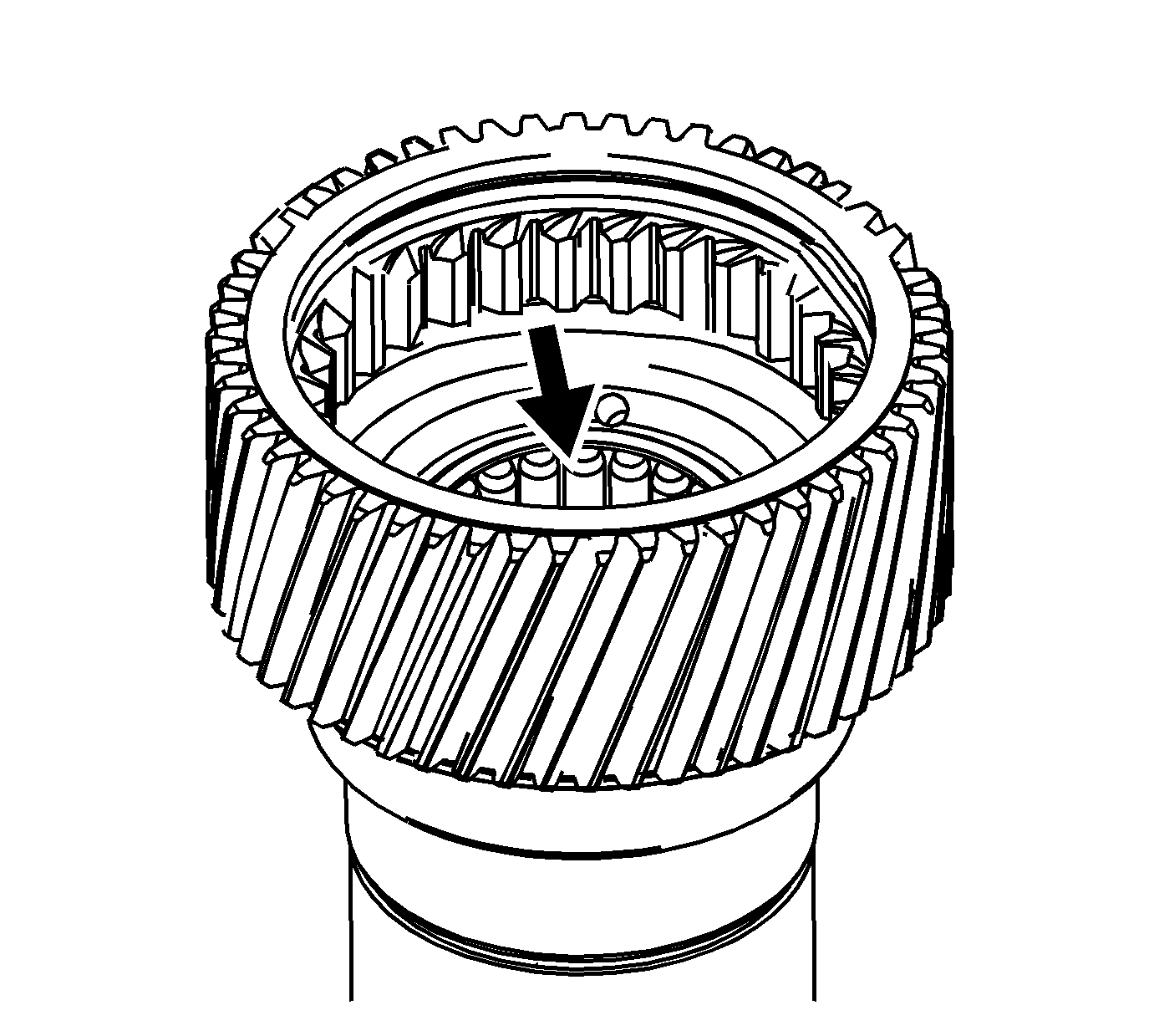
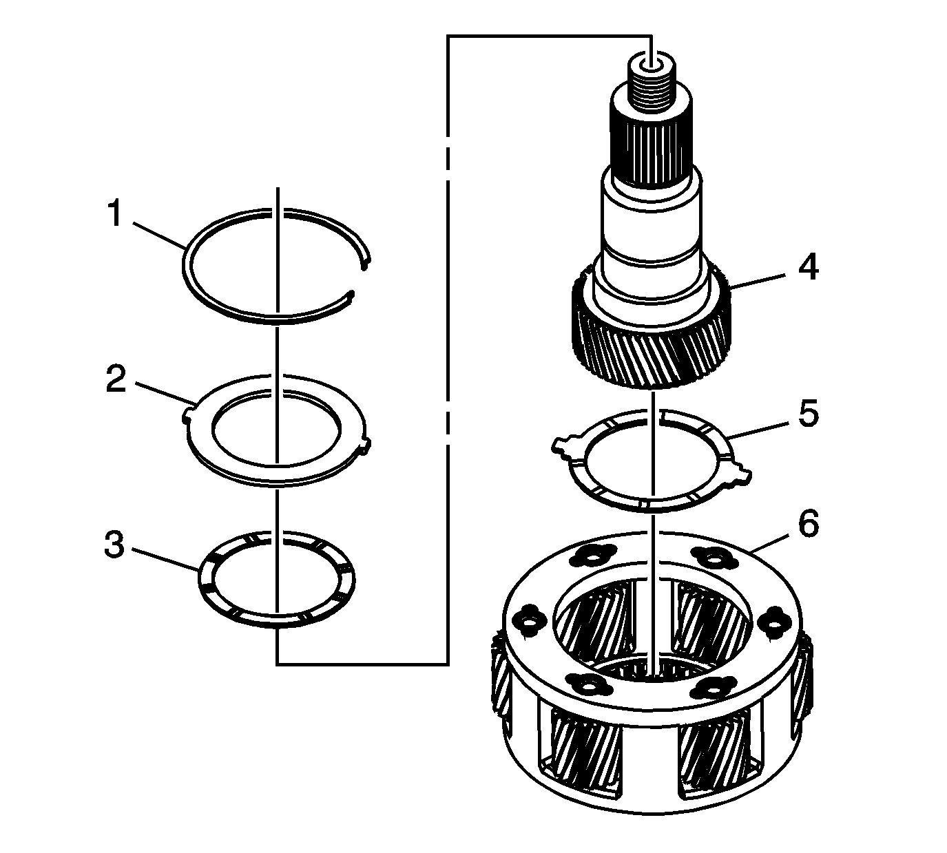
The thrust washer with the tabs must be installed.
The thrust washer without the tabs must be installed.
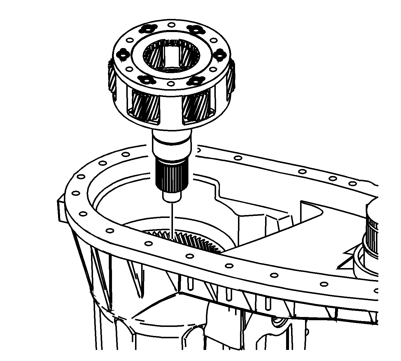
It may be necessary to use a soft-face hammer to install.
Notice: Refer to Component Fastener Tightening Notice in the Preface section.
Tighten
Tighten the shift detent bolt to 20 N·m (15 lb ft).
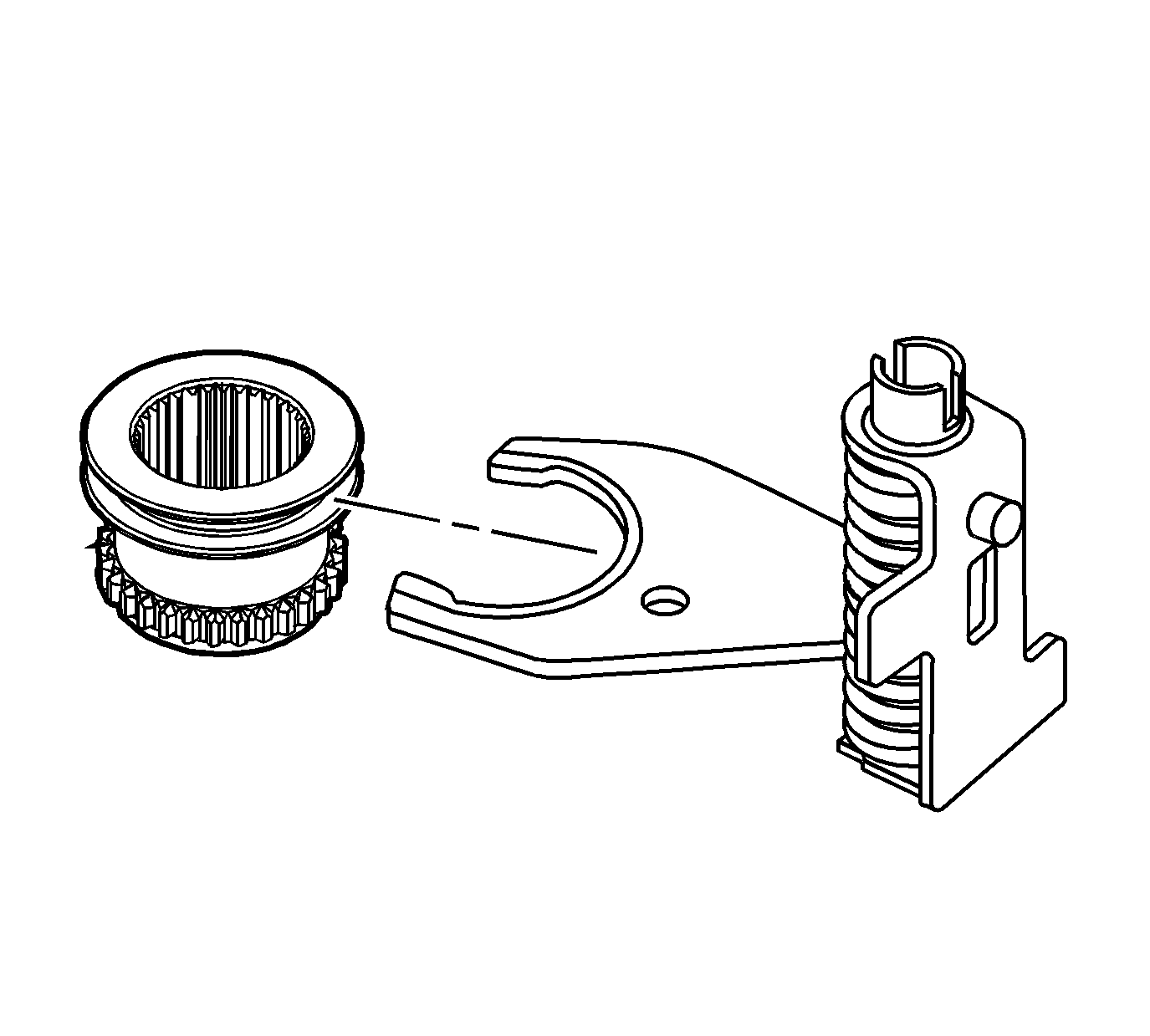
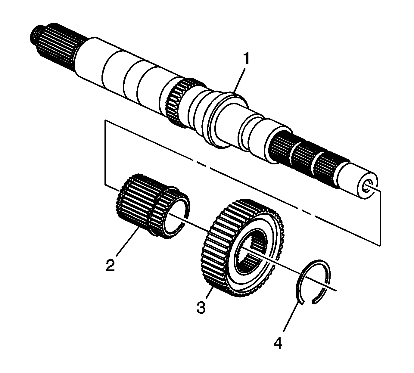
Important: Proper orientation of the drive sprocket hub (2) and synchronizer hub (3) is critical.
Ensure the ring is fully seated in the groove.
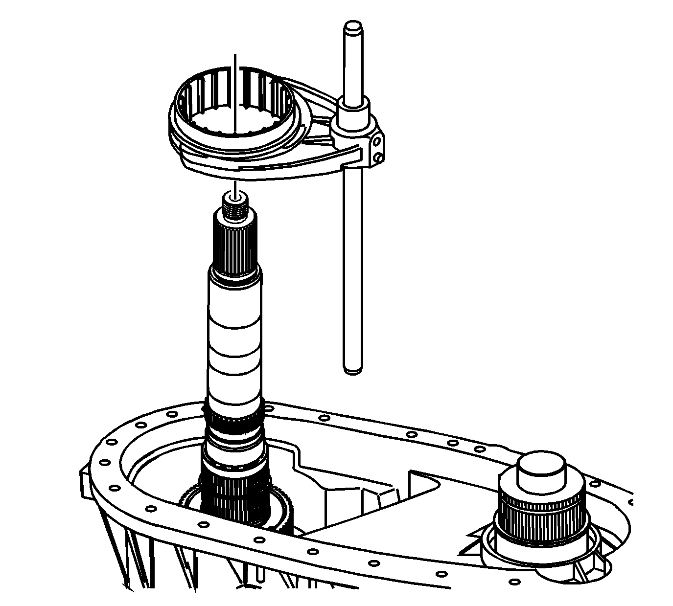
Important: Ensure the long side of the synchronizer sleeve is facing toward the planetary assembly.
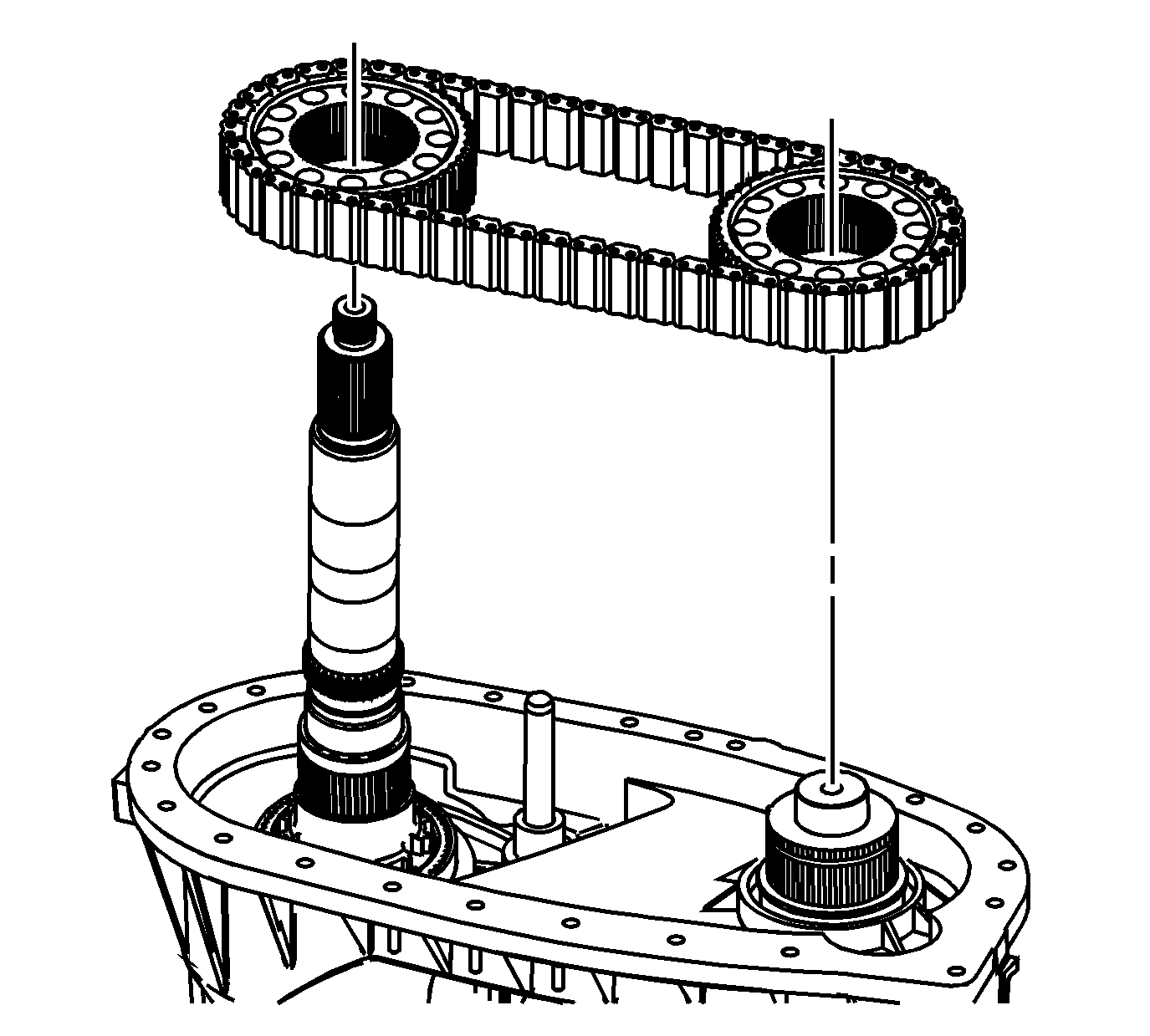
Important:
• Ensure the dark link is facing up. • If using the chain and sprockets again, align the darkened link with the marked sprockets made during disassembly.
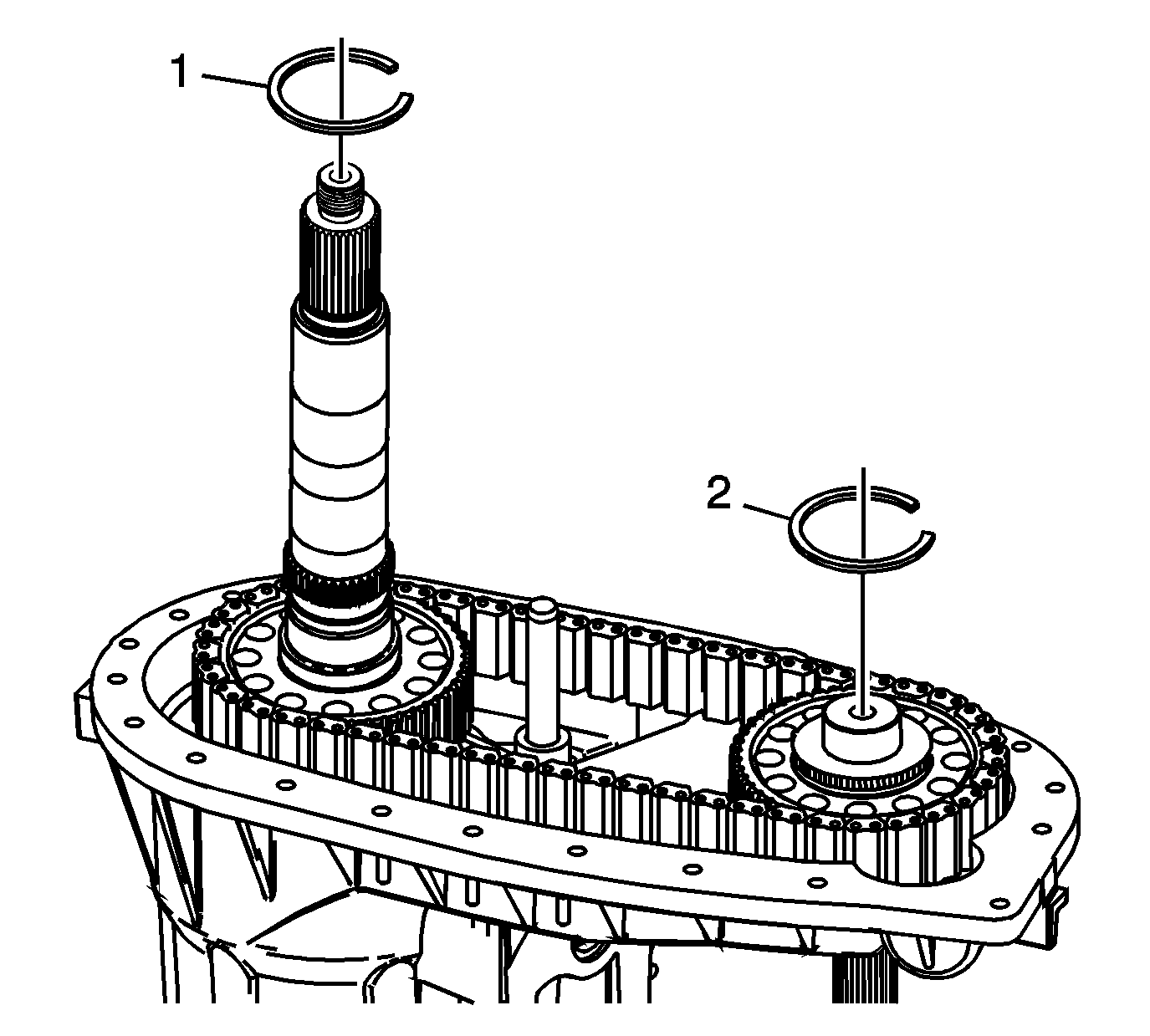
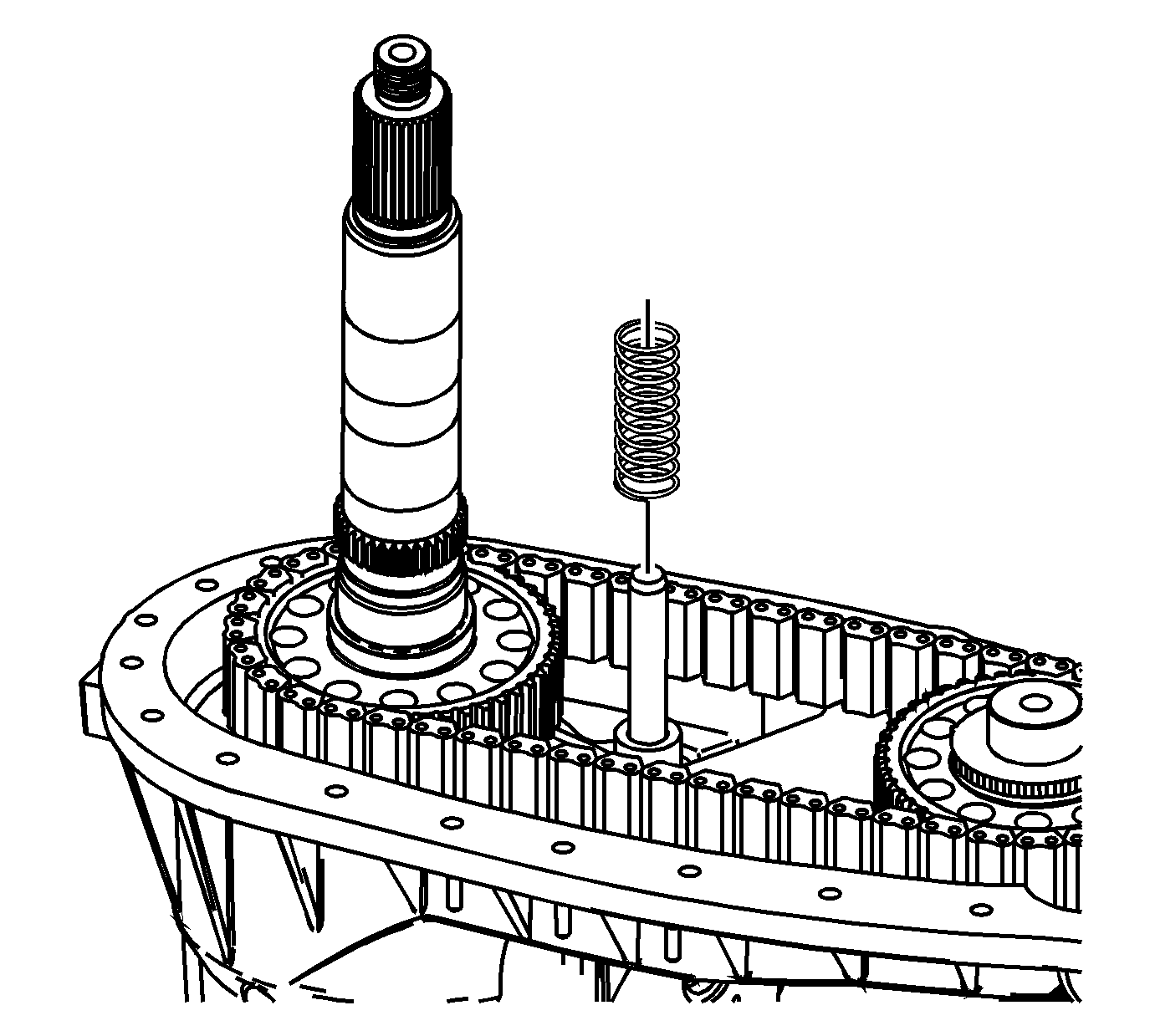
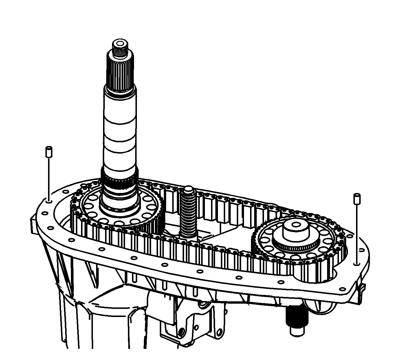
Important: Ensure the locating pins are installed in the front case half.
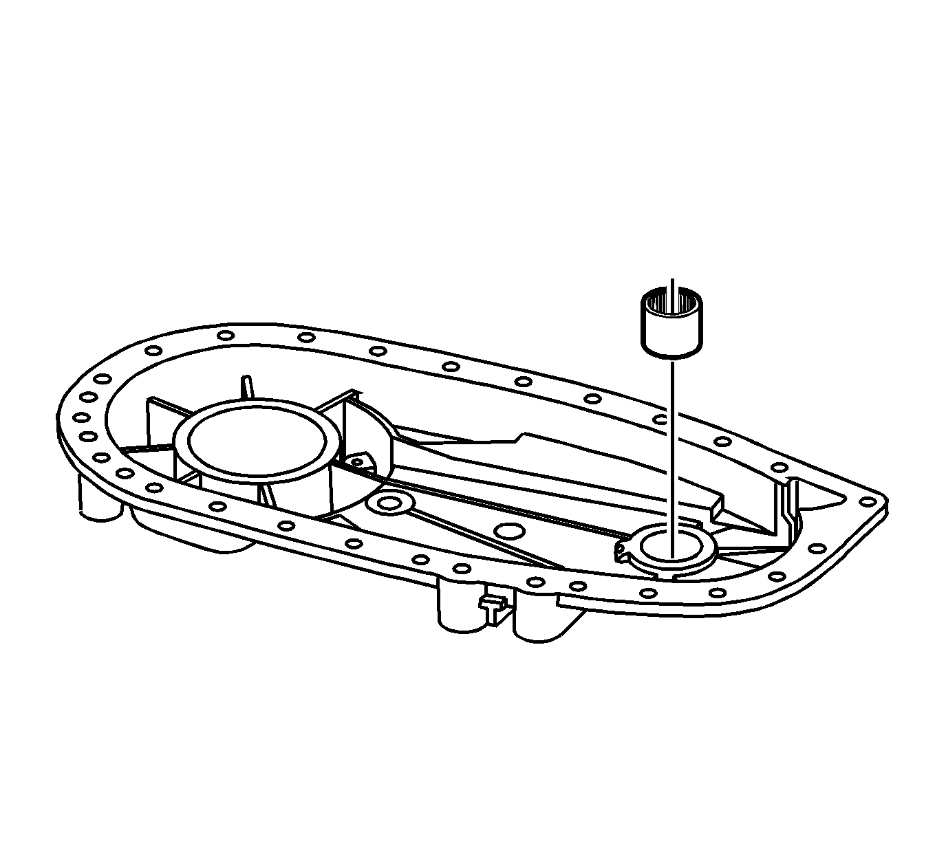
| • | The letters on the bearing face toward the tool. |
| • | Install the bearing flush with the lower edge of the chamfer. |
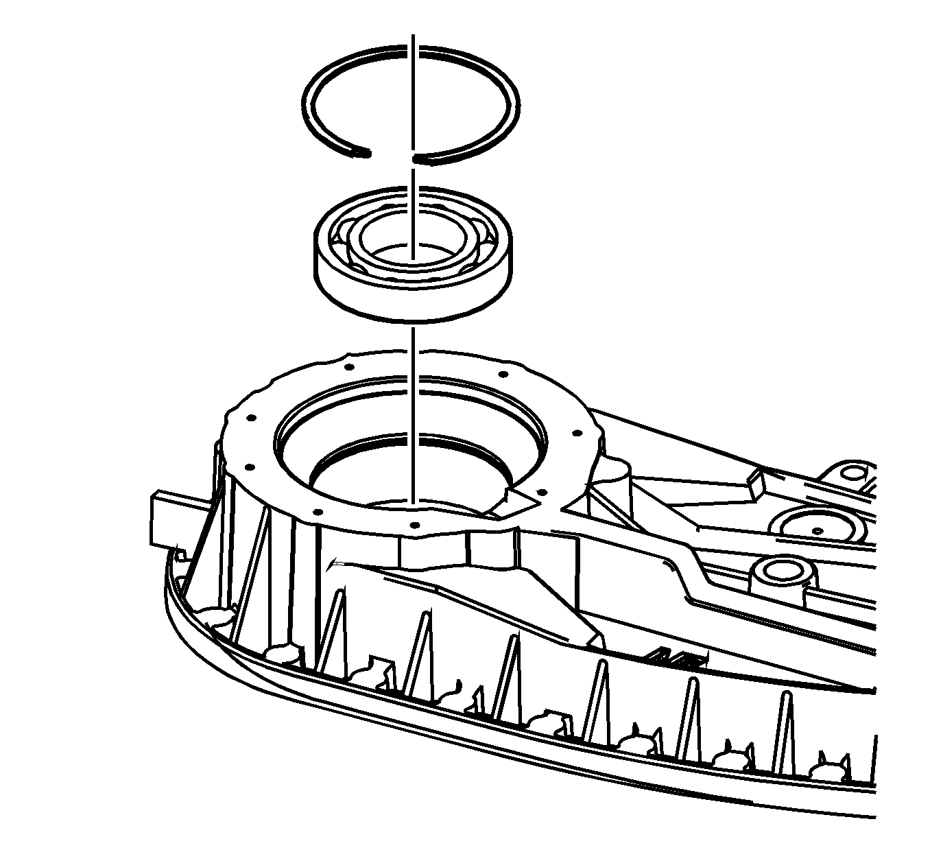
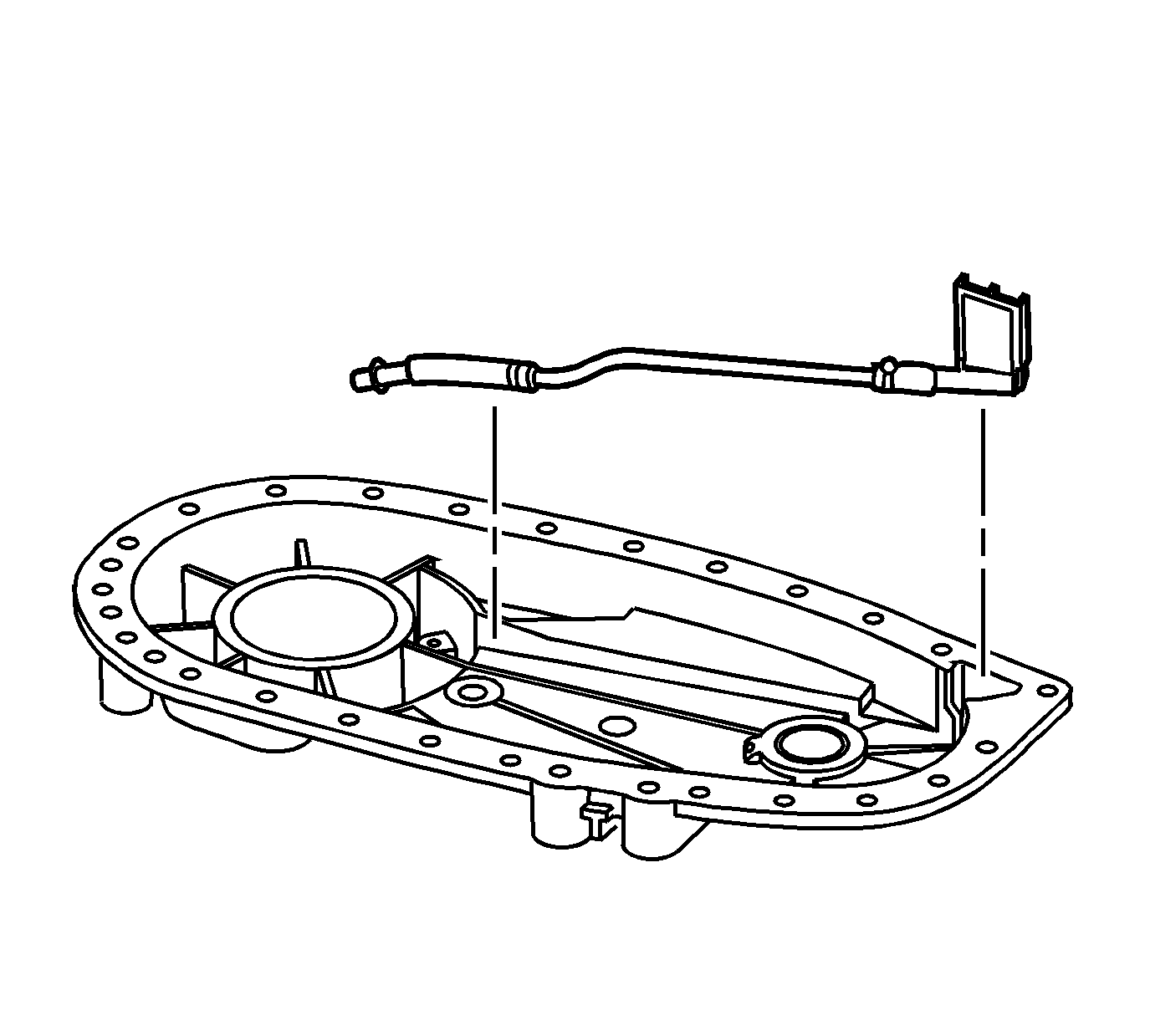
Ensure the oil pump end of the hose/pipe assembly is routed through the window in the case.
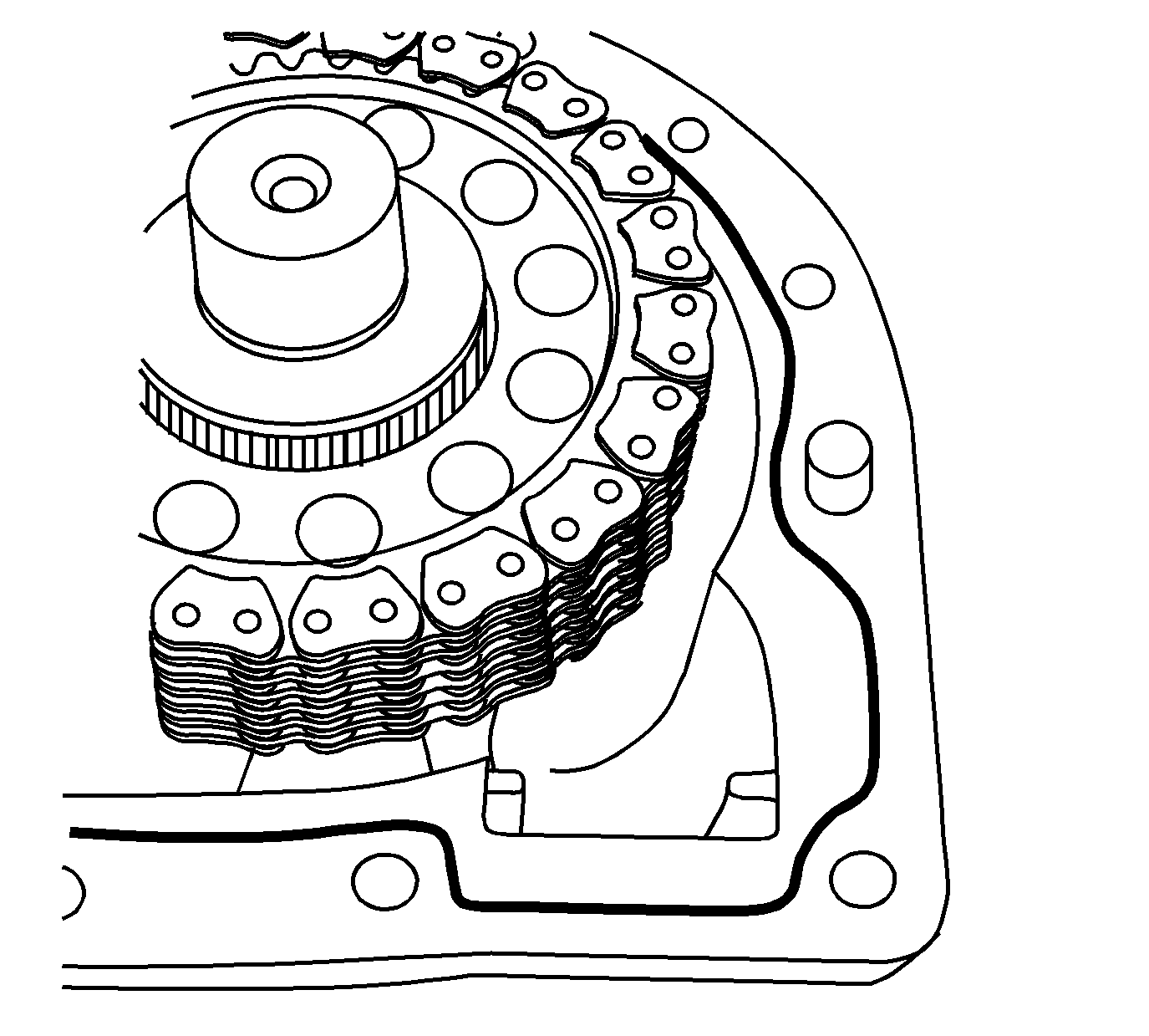
Notice: Apply the proper amount of sealant to the flange when assembling the transfer case. Excessive amounts of sealant can plug the oil pump screen, resulting in internal component failure.
Important: Ensure both sealing surfaces of the front and rear case halves are free of dirt, oil, and cleaning solvent.
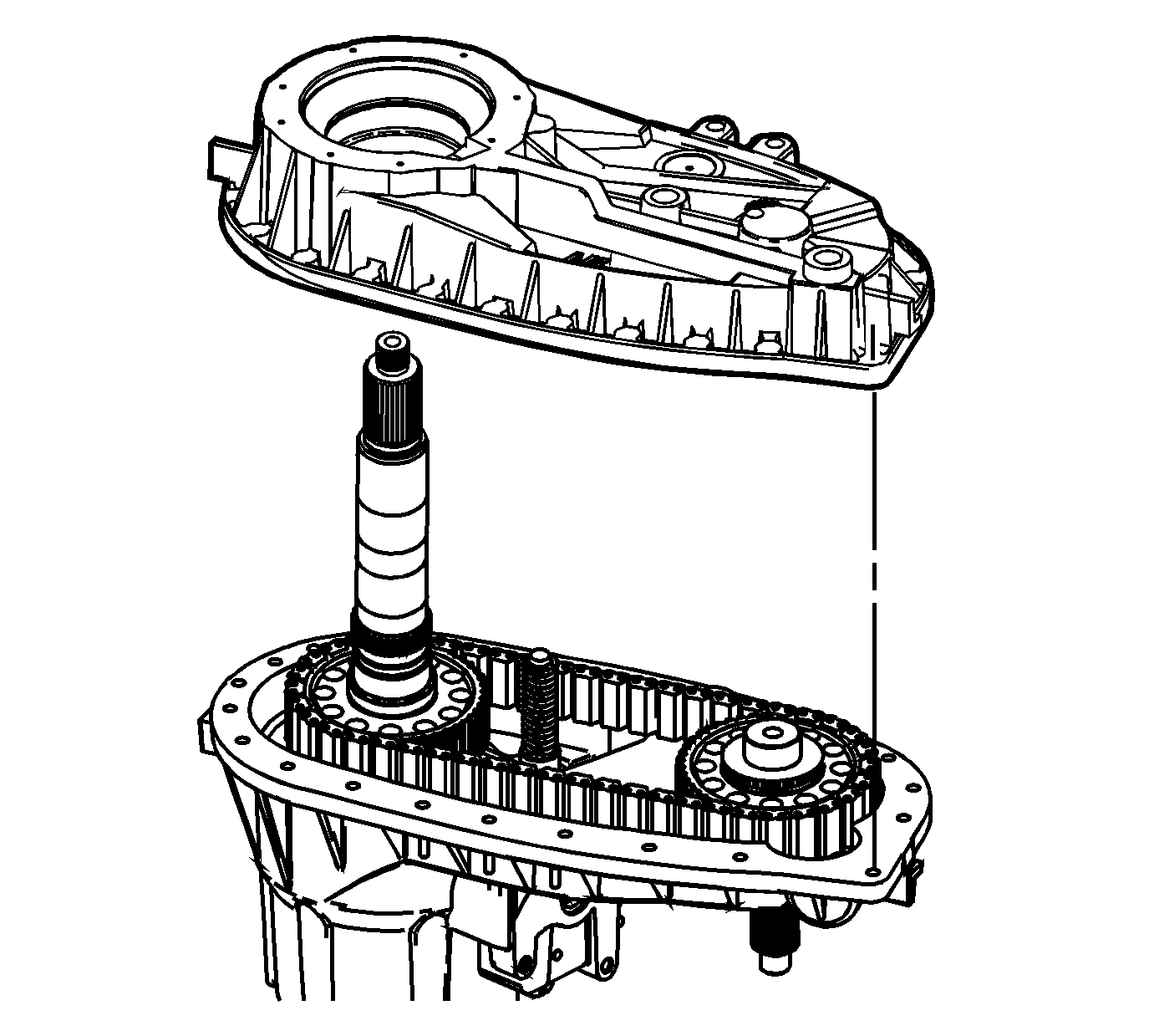
It may be necessary to lightly tap the rear case half with a rubber mallet in order to seat over the 2 dowels.
Notice: Refer to Fastener Notice in the Preface section.
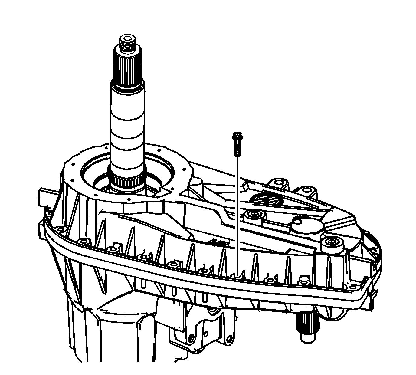
Tighten
Tighten the case half bolts to 27 N·m (20 lb ft).
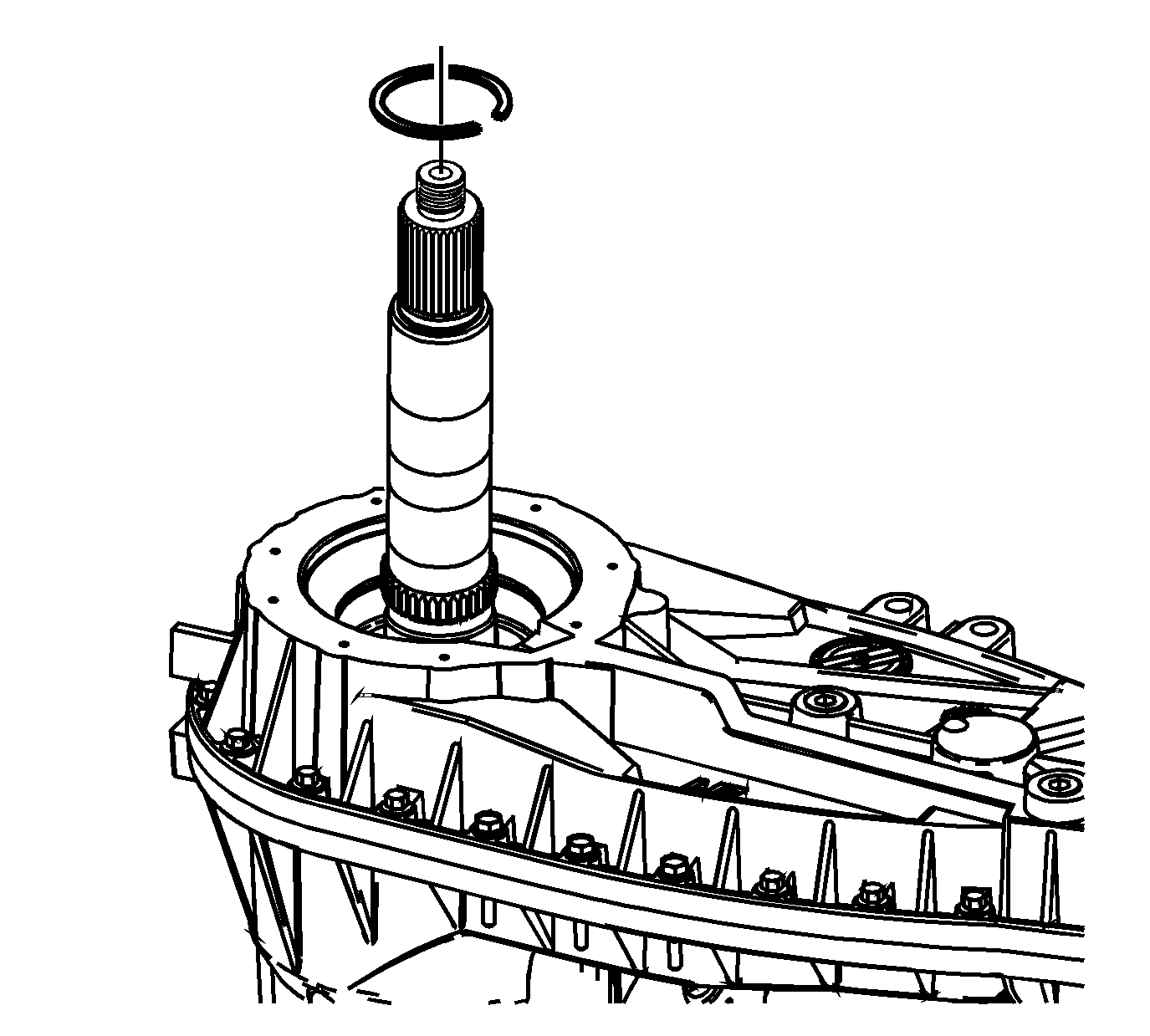
Ensure the ring is fully seated in the groove.
Important:
• Do not grasp the upper connection hose (1). • Use care not to tear the O-ring seal.
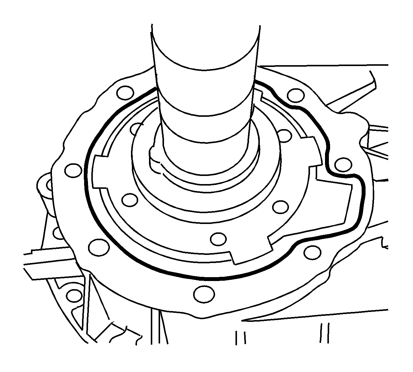
Notice: Apply the proper amount of sealant to the flange when assembling the transfer case. Excessive amounts of sealant can plug the oil pump screen, resulting in internal component failure.
Important: Ensure both sealing surfaces of the rear case half and retainer assembly are free of dirt, oil, and cleaning solvent.
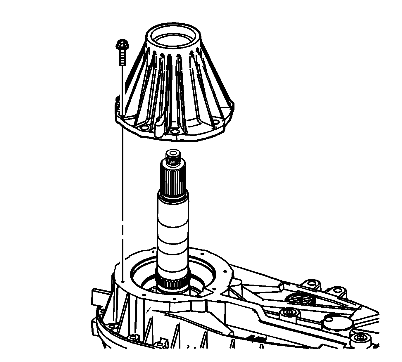
Tighten
Tighten the retainer assembly bolts to 30 N·m (22 lb ft).
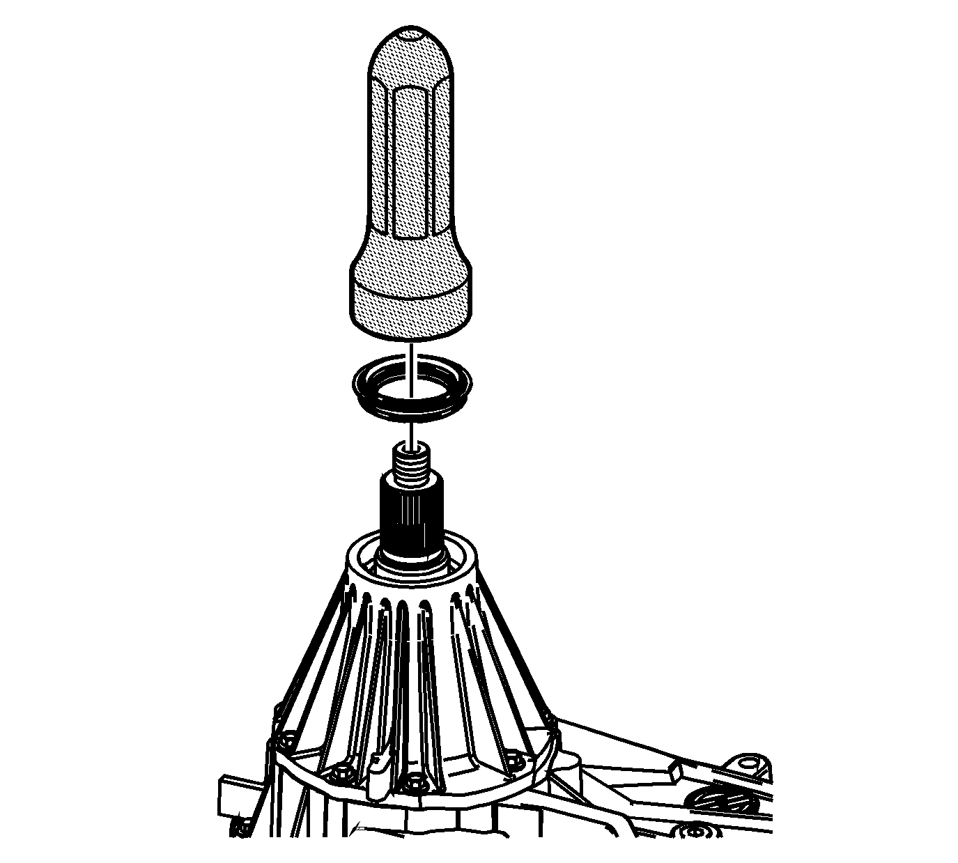
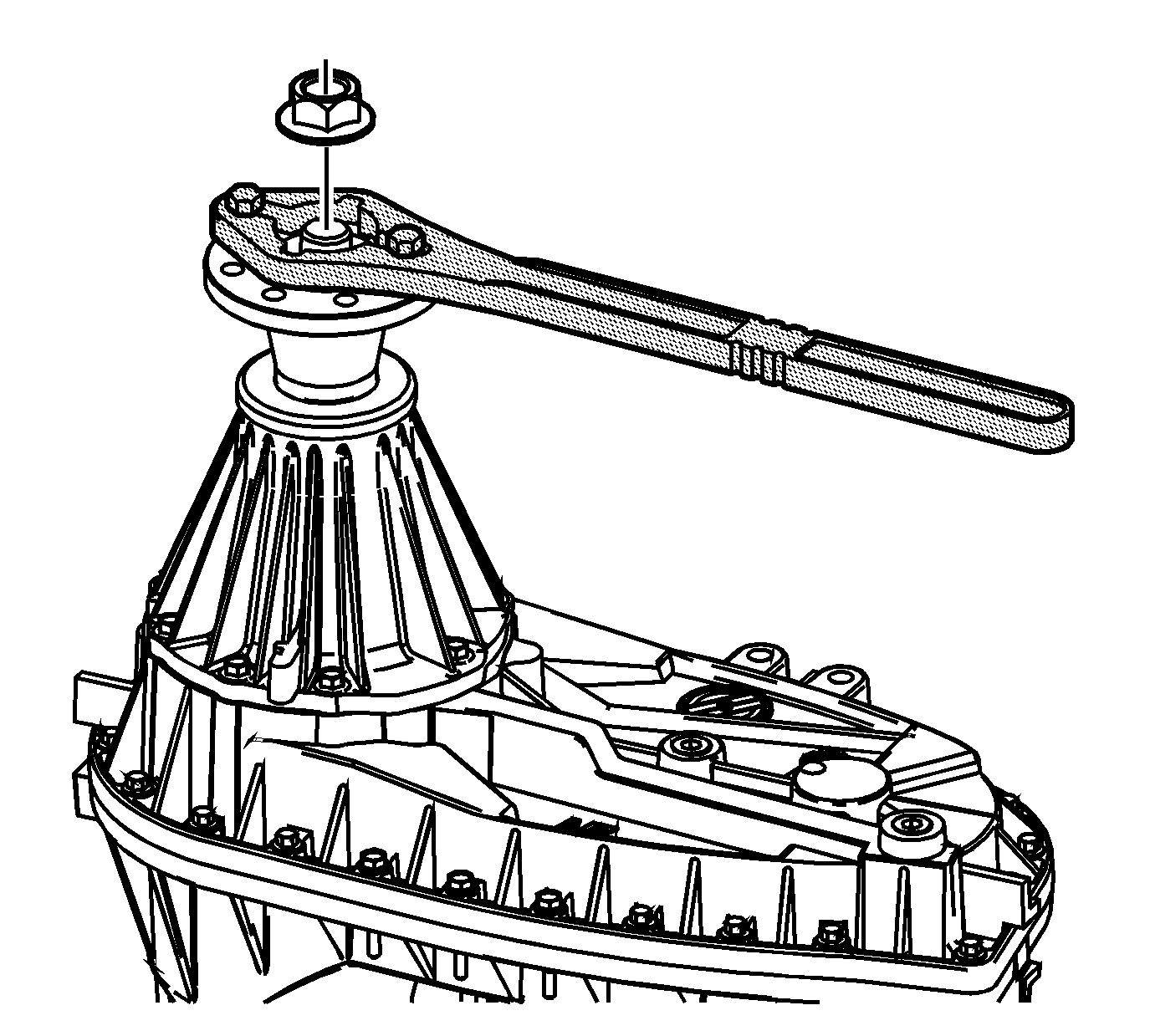
Tighten
Tighten the rear output flange nut to 251 N·m (185 lb ft).
Tighten
Tighten the front output flange nut to 224 N·m (165 lb ft).
Tighten
Tighten the input flange nut to 251 N·m (185 lb ft).
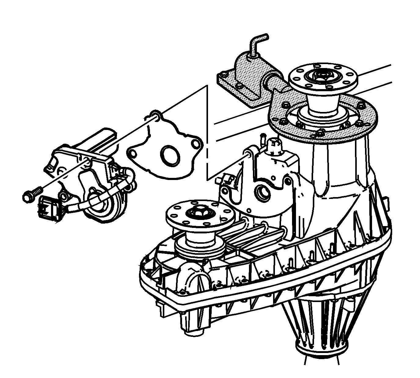
Important: Ensure the alignment sleeve is in position.
Tighten
Tighten the actuator encoder motor mounting bolts to 20 N·m (15 lb ft).
Tighten
Tighten the drain plug to 20 N·m (15 lb ft).
Tighten
Tighten the fill plug to 20 N·m (15 lb ft).
