For 1990-2009 cars only
Inspection Procedure
Test the relay circuit for voltage with the relay removed. Use a voltmeter to inspect for system voltage at cavities B and 30. Cavity 30 is hot at all times. Cavity B is energized by the engine control switch.
Use an ohmmeter to test cavities A and 31. Cavity A is the ground side for the relay. Cavity 31 is the load side, glow plugs, of the relay.
The relays load side can be inspected for high resistance with an ohmmeter. The reading should be 0.1 ohms or less. If the resistance is higher, replace the relay.
Removal Procedure
- Disconnect the negative battery cable. Refer to Battery Negative Cable Disconnection and Connection .
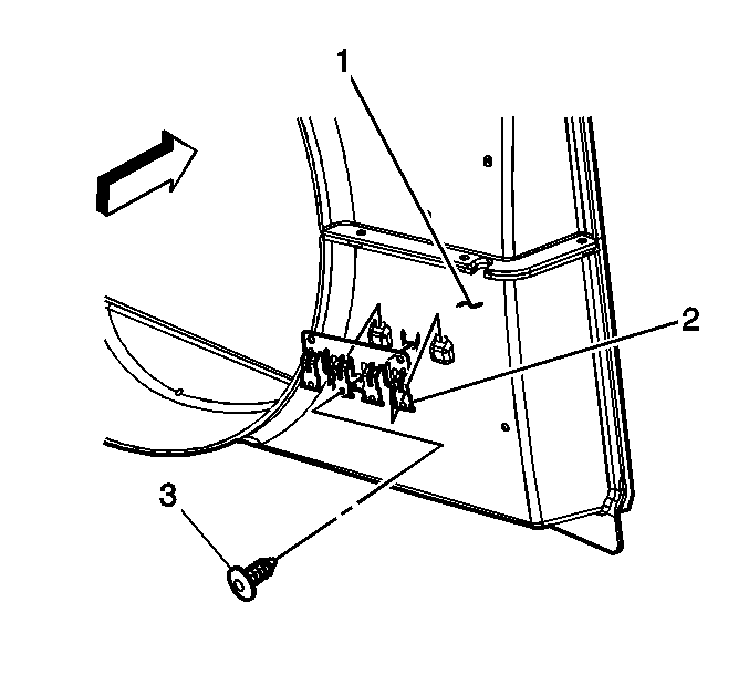
- Remove the glow plug relay from the bracket (2).
Caution: Refer to Battery Disconnect Caution in the Preface section.

Installation Procedure
- Install the glow plug relay to the bracket (2).
- Connect the negative battery cable.

