Removal Procedure
Important: Do not raise the engine by the crankshaft balancer to perform this service procedure. Damage to the crankshaft balancer or the crankshaft may occur.
- Drain the engine oil. Refer to Engine Oil and Oil Filter Replacement .
- Remove the oil level indicator tube. Refer to Oil Level Indicator and Tube Replacement .
- Remove the starter motor. Refer to Starter Motor Replacement .
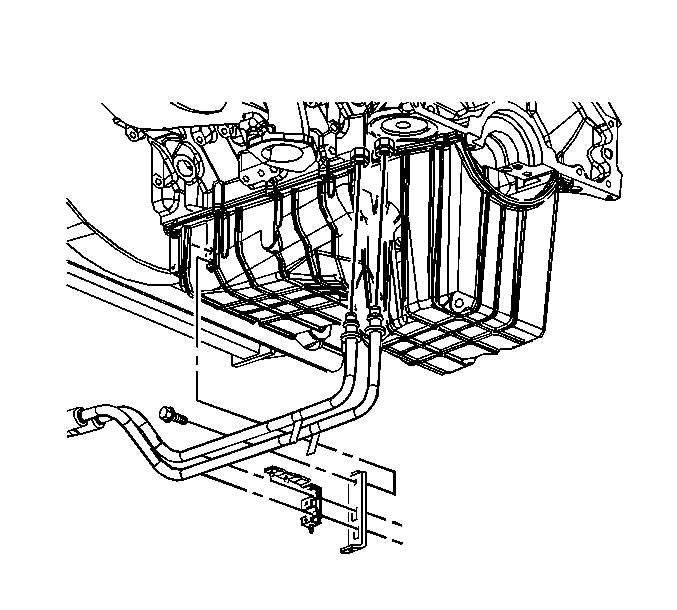
- Remove the oil cooler line bracket bolt.
- Remove the oil cooler line bracket from the oil pan.
- Remove the transmission fluid cooler line clip bolt.
- Remove the transmission fluid cooler line bracket bolt and bracket.
- Disconnect the oil level switch electrical connector.
- Remove the oil level switch from the oil pan.
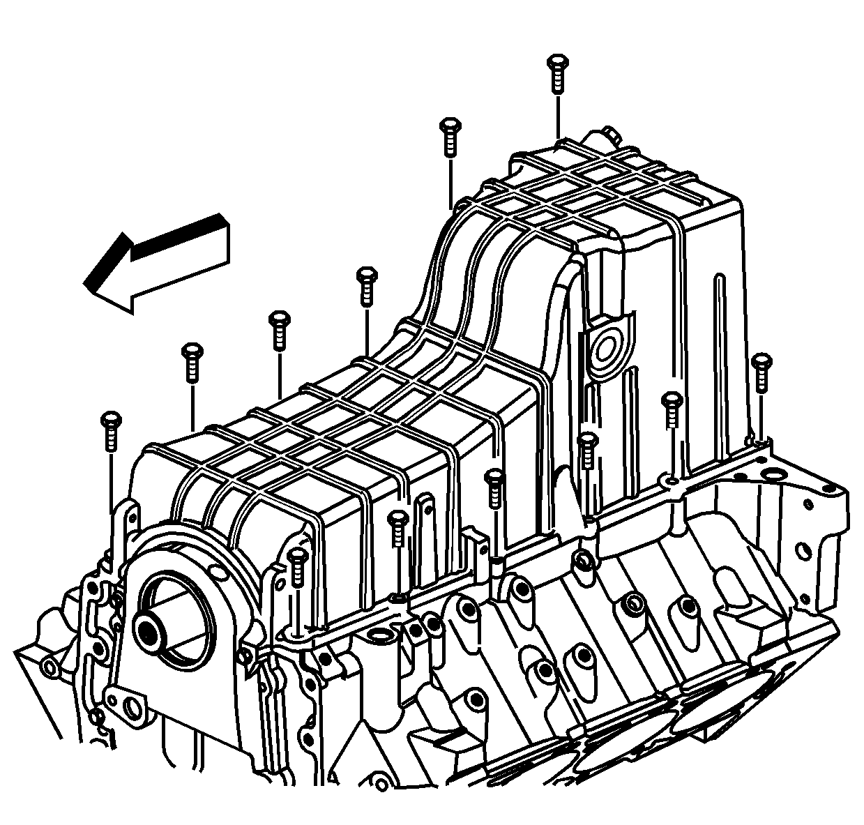
- Remove the oil pan bolts.
- Remove the oil pan (1) and the captured oil pan gasket (2).
- Clean and inspect the oil pan.
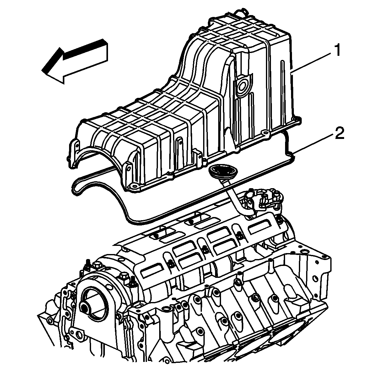
Important: The oil pan gasket is reusable if not cut or damaged.
Installation Procedure
Important: The oil pan must be installed within 5 minutes of the sealer being applied or the sealer will begin to cure, causing an inadequate seal.
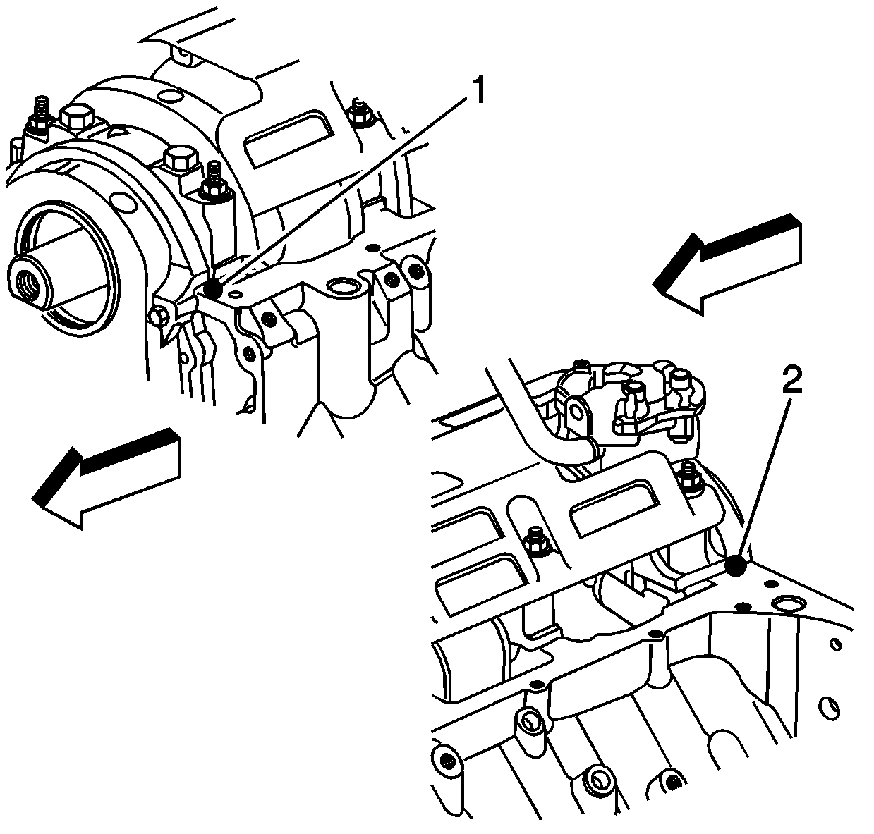
- Apply sealant to the side of the front (1) and rear (2) crankshaft bearing caps, on both the left and right sides (4 locations total). Refer to Adhesives, Fluids, Lubricants, and Sealers for the correct part number.
- Install a new oil pan gasket (2) into the oil pan groove, if necessary.
- Install the oil pan (1).
- Install the oil pan bolts.
- Tighten the oil pan bolt in sequence a first pass to 10 N·m (89 lb in).
- Tighten the oil pan bolts in sequence a final pass to 25 N·m (18 lb ft).
- Install the transmission fluid cooler line bracket bolt and bracket.
- Install the transmission fluid cooler line clip bolt.
- Install the oil level switch to the oil pan.
- Connect the oil level switch electrical connector.
- Install the oil cooler line bracket to the oil pan.
- Install the oil cooler line bracket bolt.
- Install the starter motor. Refer to Starter Motor Replacement .
- Install the oil level indicator. Refer to Oil Level Indicator and Tube Replacement .
- Fill the engine with oil. Refer to Engine Oil and Oil Filter Replacement .

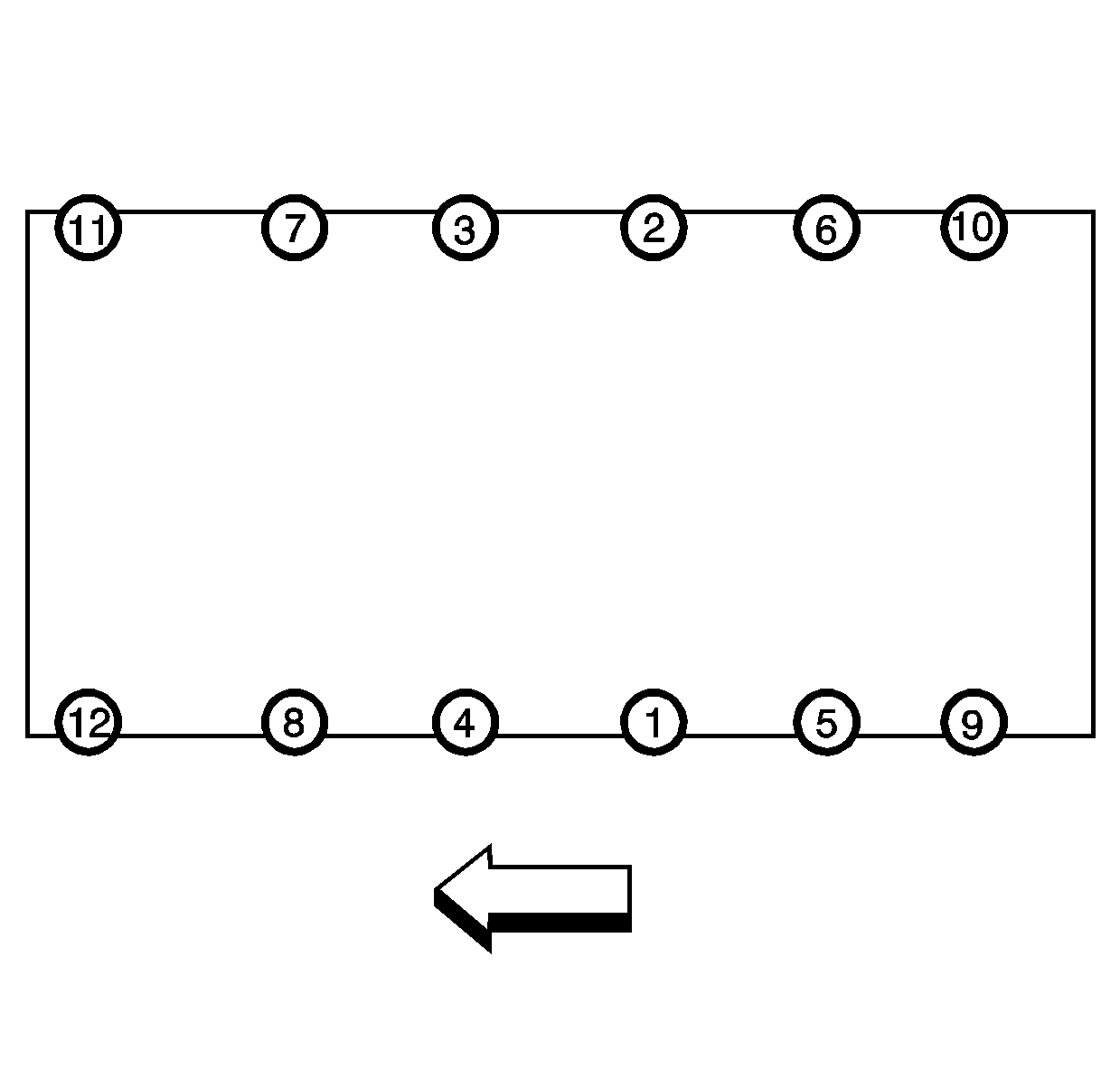
Notice: Use the correct fastener in the correct location. Replacement fasteners must be the correct part number for that application. Fasteners requiring replacement or fasteners requiring the use of thread locking compound or sealant are identified in the service procedure. Do not use paints, lubricants, or corrosion inhibitors on fasteners or fastener joint surfaces unless specified. These coatings affect fastener torque and joint clamping force and may damage the fastener. Use the correct tightening sequence and specifications when installing fasteners in order to avoid damage to parts and systems.
Tighten
Tighten
Tighten the transmission fluid cooler line bracket bolt to 30 N·m (22 lb ft).
Tighten
Tighten the transmission fluid cooler line clip bolt to 30 N·m (22 lb ft).
Tighten
Tighten the oil level switch to 14 N·m (10 lb ft).

Tighten
Tighten the oil cooler line bracket bolt to 9 N·m (80 lb in).
