GM Service Manual Online
For 1990-2009 cars only
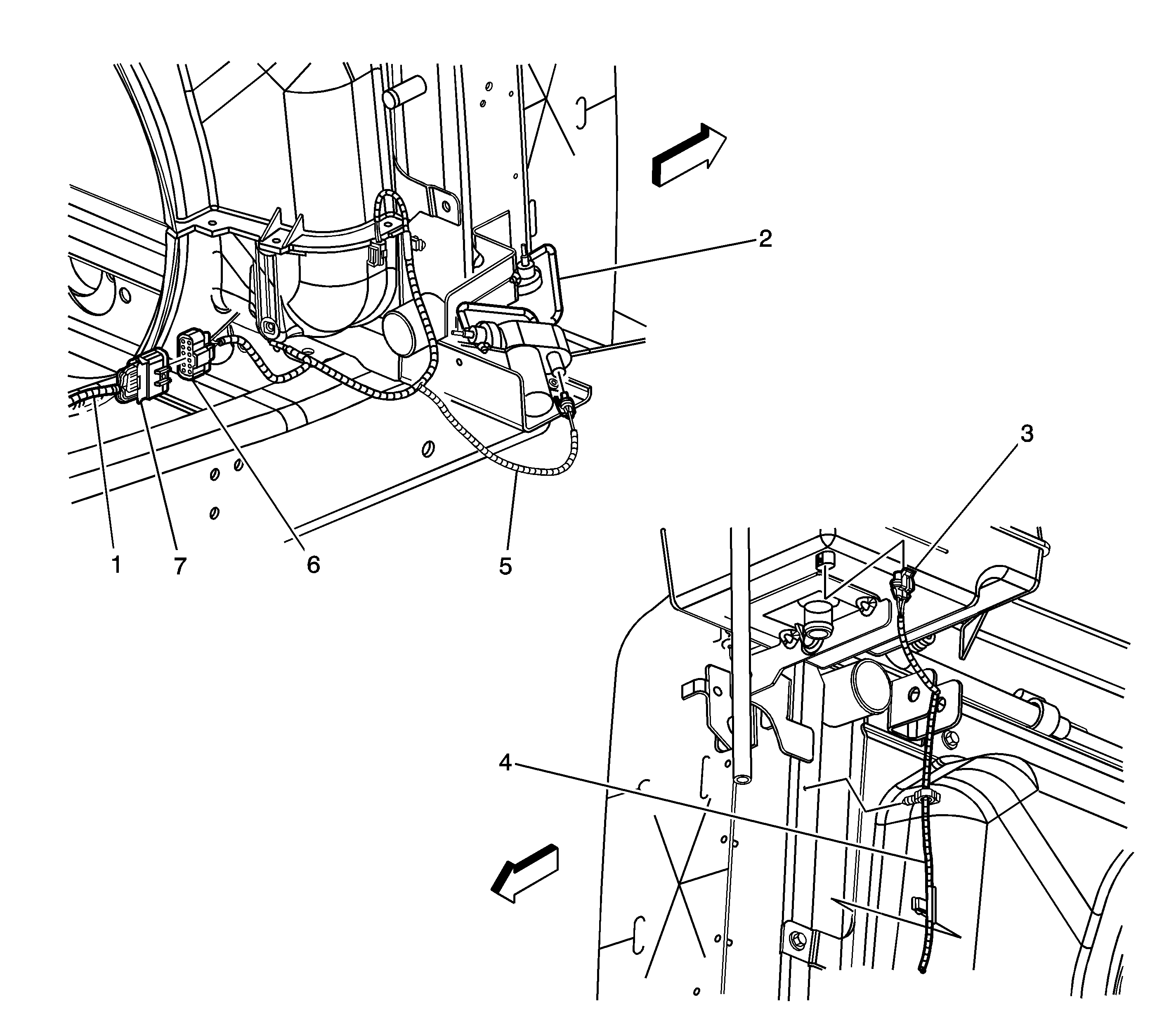
Figure 1:

Front of Vehicle


Object Number: 826867  Size: LF
(1)Chassis Harness
(2)Vacuum Pump
(3)Coolant Level Switch Connector
(4)Engine Fan Harness
(5)Vacuum Pump Connector
(6)C106
(7)C106
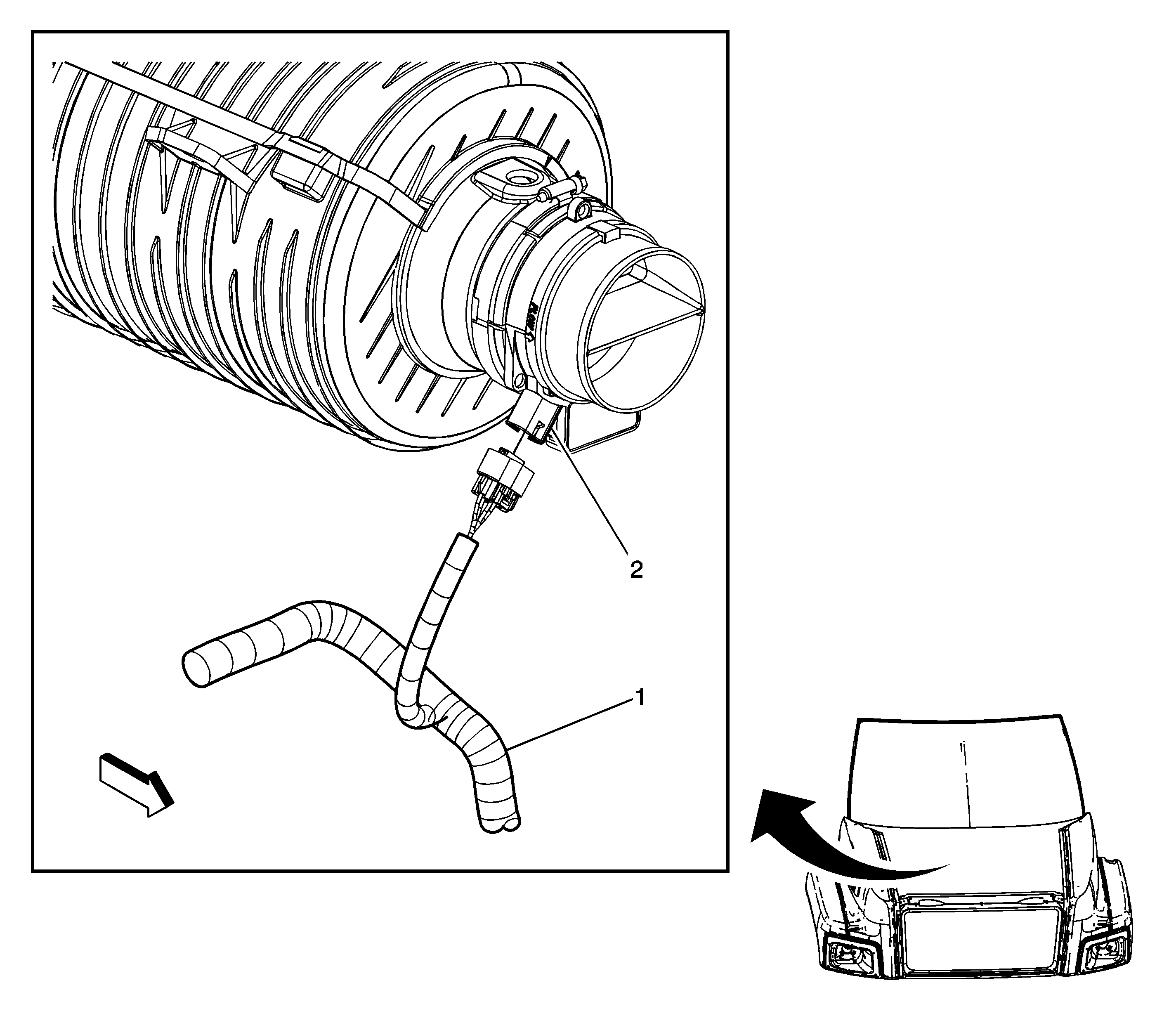
Figure 2:

Air Cleaner Assembly


Object Number: 822049  Size: LF
(1)Engine Chassis Harness
(2)Mass Air Flow (MAF)/Intake Air Temperature (IAT) Sensor
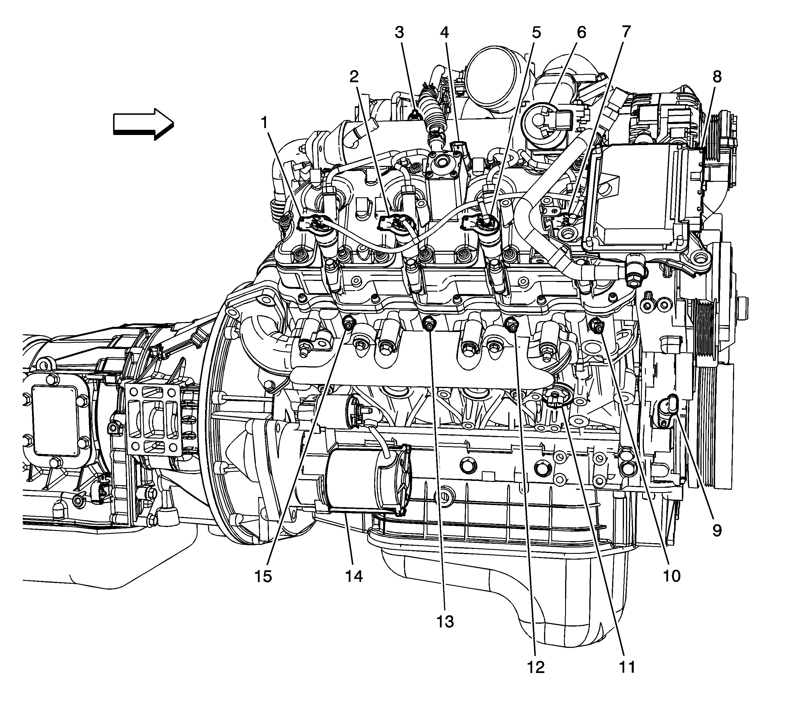
Figure 3:

Right Side of Engine


Object Number: 1807997  Size: LF
(1)Fuel Injector 7
(2)Fuel Injector 5
(3)Turbocharger Vane Position (TVP) Control Solenoid Valve
(4)Fuel Rail Pressure (FRP) Sensor
(5)Fuel Injector 3
(6)Exhaust Valve Recirculation (EGR) Valve
(7)Fuel Injector 1
(8)Fuel Injection Control Module (FICM)
(9)Crankshaft Position (CKP) Sensor
(10)Glow Plug 1
(11)Block Heater
(12)Glow Plug 3
(13)Glow Plug 5
(14)Starter
(15)Glow Plug 7
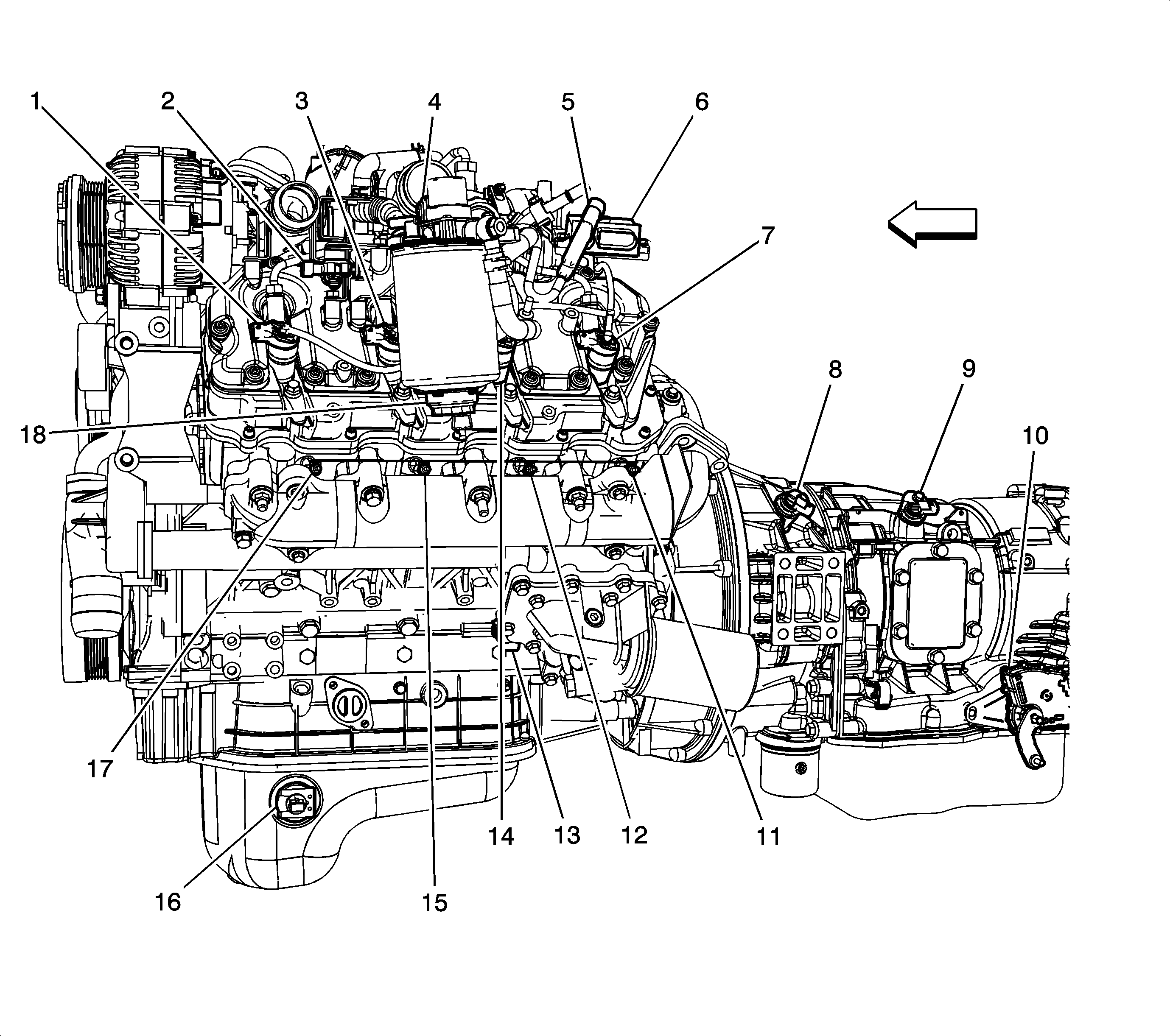
Figure 4:

Left Side of Engine


Object Number: 1808005  Size: LF
(1)Fuel Injector 2
(2)Barometric Pressure (Baro) Sensor
(3)Fuel Injector 4
(4)Fuel Heater
(5)Turbocharger Vane Position (TVP) Sensor
(6)Glow Plug Controller
(7)Fuel Injector 8
(8)Turbine Shaft Speed (TSS) Sensor
(9)Automatic Transmission Input Shaft Speed (AT ISS) Sensor
(10)Park/Neutral Position (PNP) Switch
(11)Glow Plug 8
(12)Glow Plug 6
(13)Engine Oil Pressure (EOP) Sensor
(14)Fuel Injector 6
(15)Glow Plug 4
(16)Engine Oil Level Switch
(17)Glow Plug 2
(18)Water-in-Fuel Sensor
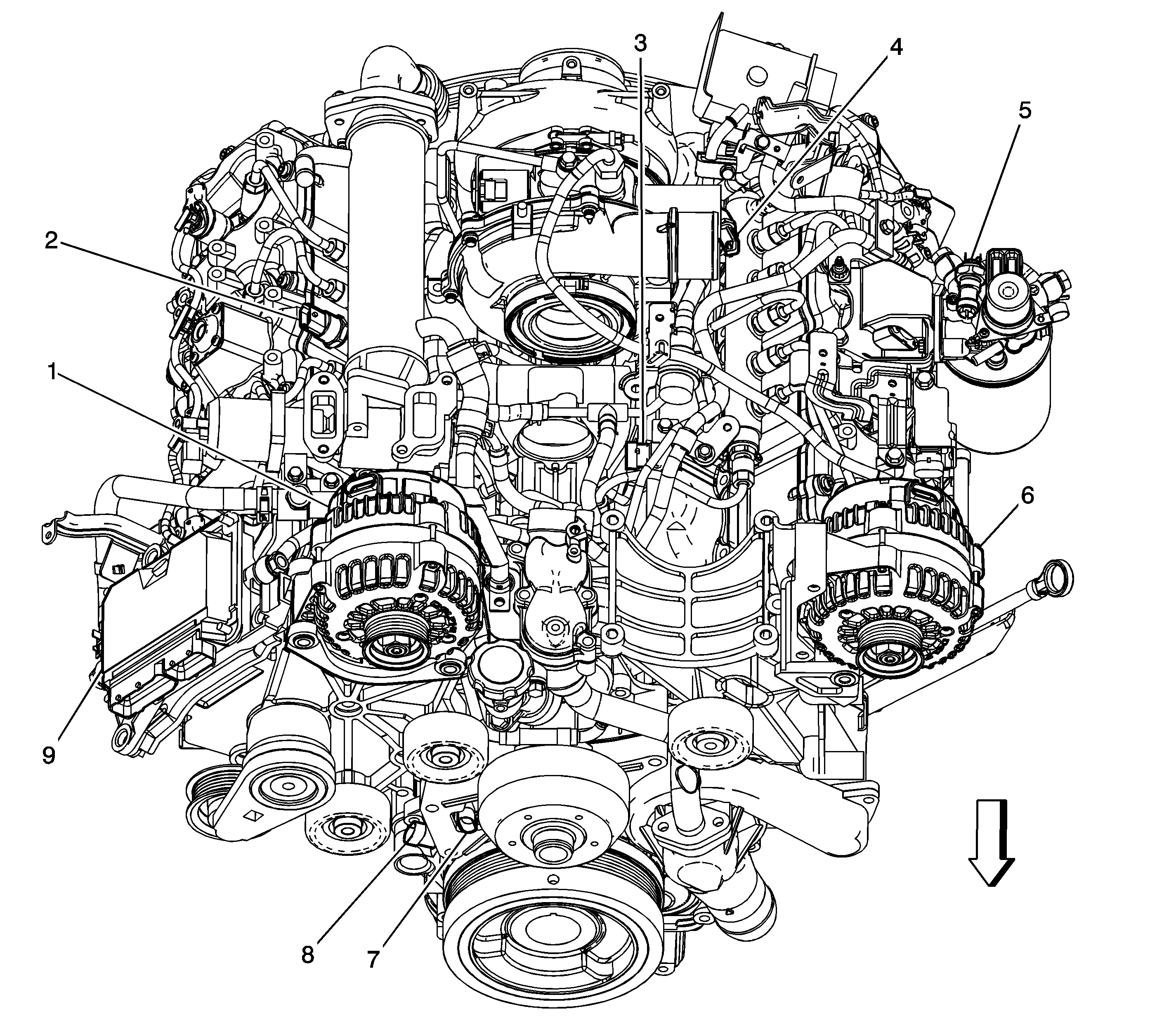
Figure 5:

Top of Engine


Object Number: 1808008  Size: LF
(1)Generator - Right (K65)
(2)Fuel Rail Pressure (FRP) Sensor
(3)Manifold Absolute Pressure (MAP) Sensor
(4)Fuel Temperature Sensor
(5)Fuel Heater
(6)Generator - Left
(7)Camshaft Position (CMP) Sensor
(8)Crankshaft Position (CKP) Sensor
(9)Fuel Injection Control Module (FICM)
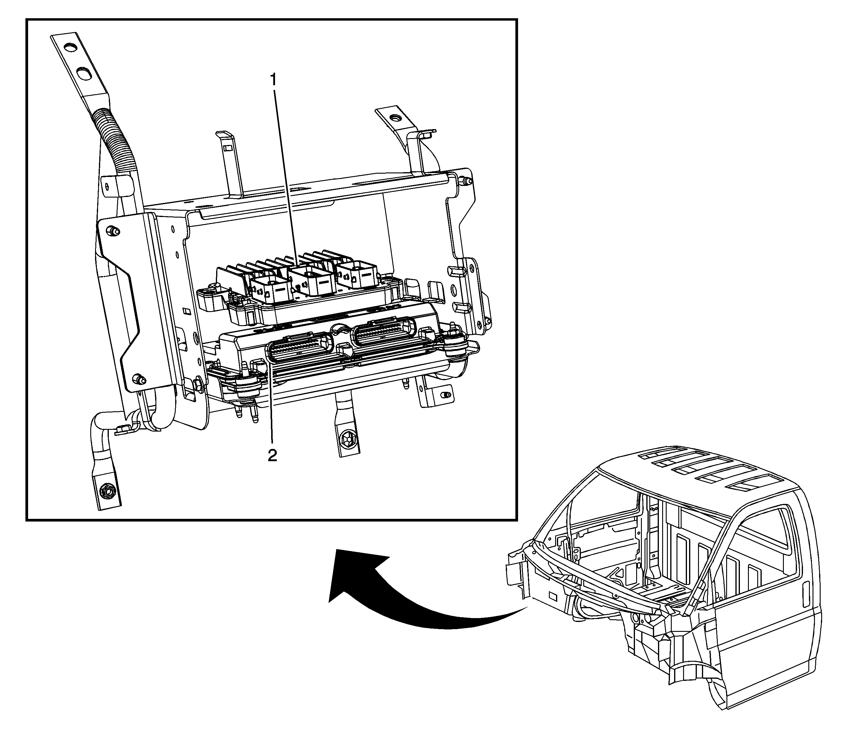
Figure 6:

ECM/TCM View


Object Number: 1422659  Size: LF
(1)Engine Control Module (ECM)
(2)Transmission Control Module (TCM)
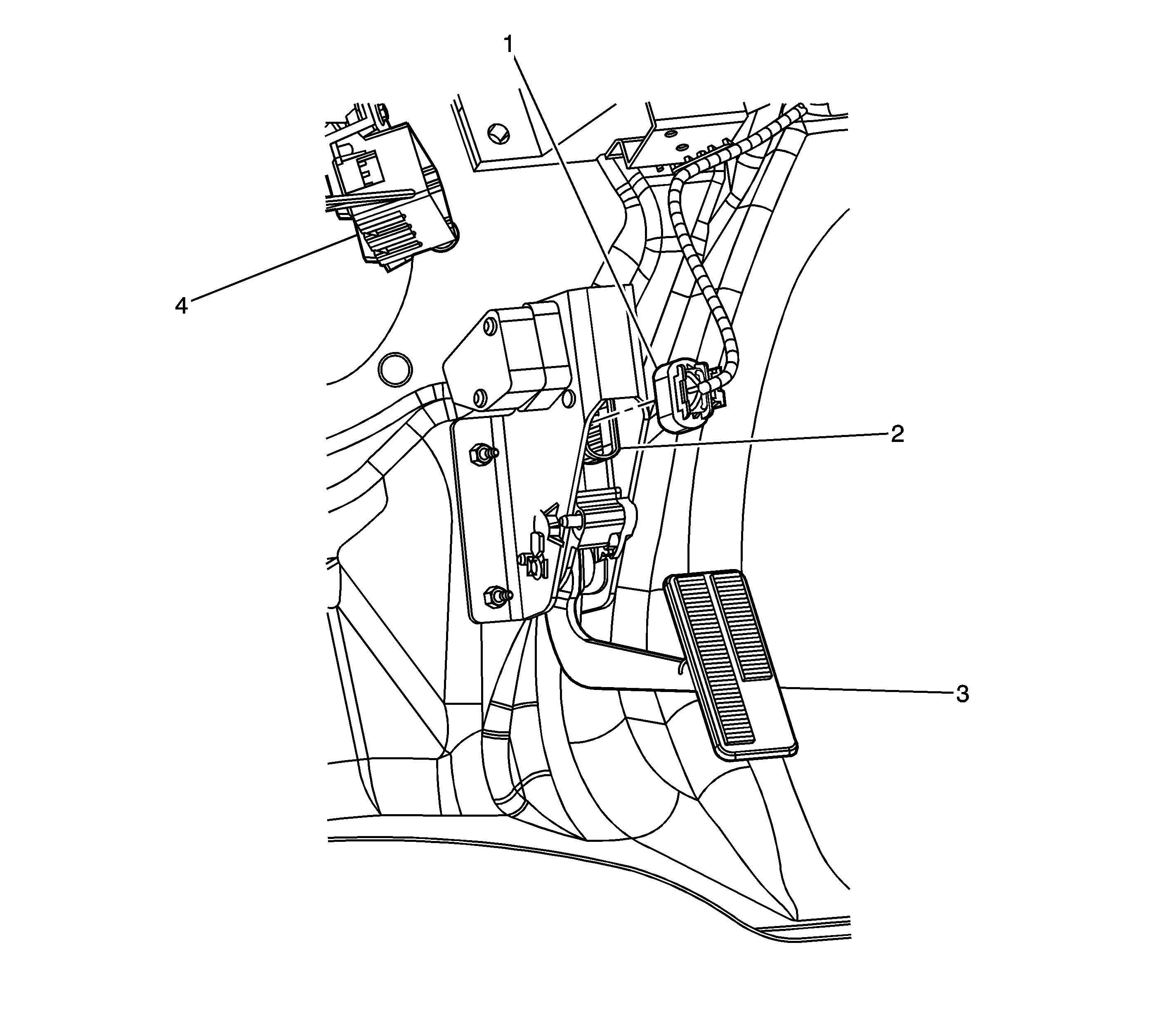
Figure 7:

Accelerator Pedal


Object Number: 1155067  Size: LF
(1)Accelerator Pedal Position (APP) Sensor Connector
(2)Accelerator Pedal Position (APP) Sensor
(3)Accelerator Pedal
(4)C201 (48 cavities)
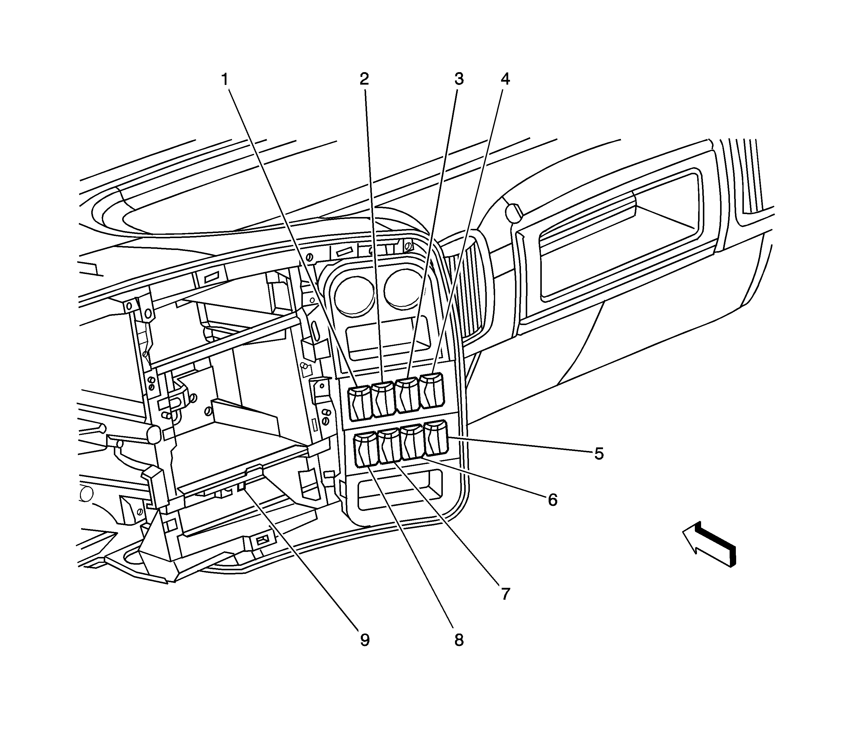
Figure 8:

Center and the Right I/P


Object Number: 1430017  Size: LF
(1)Marker Lamp Switch (RQ2 and U86 or RQ2)
(2)High Idle Switch (UF3)
(3)Traction Control Switch (NW9)
(4)Outside Heated Mirror Switch (DB6/DB8)
(5)Exhaust Brake Switch (K40)
(6)Rear Axle Driver Control Switch - Two Speed (HPZ/Automatic Transmission)
(7)Air Suspension Dump Switch (G40/G45/GSJ)
(8)Power Take-Off (PTO) Switch
(9)Driver Information Center (DIC)
Figure 9:

Air Compressor (K16), Fuel Tanks and Trailer Connector (RQ2 and U86 or RQ3)
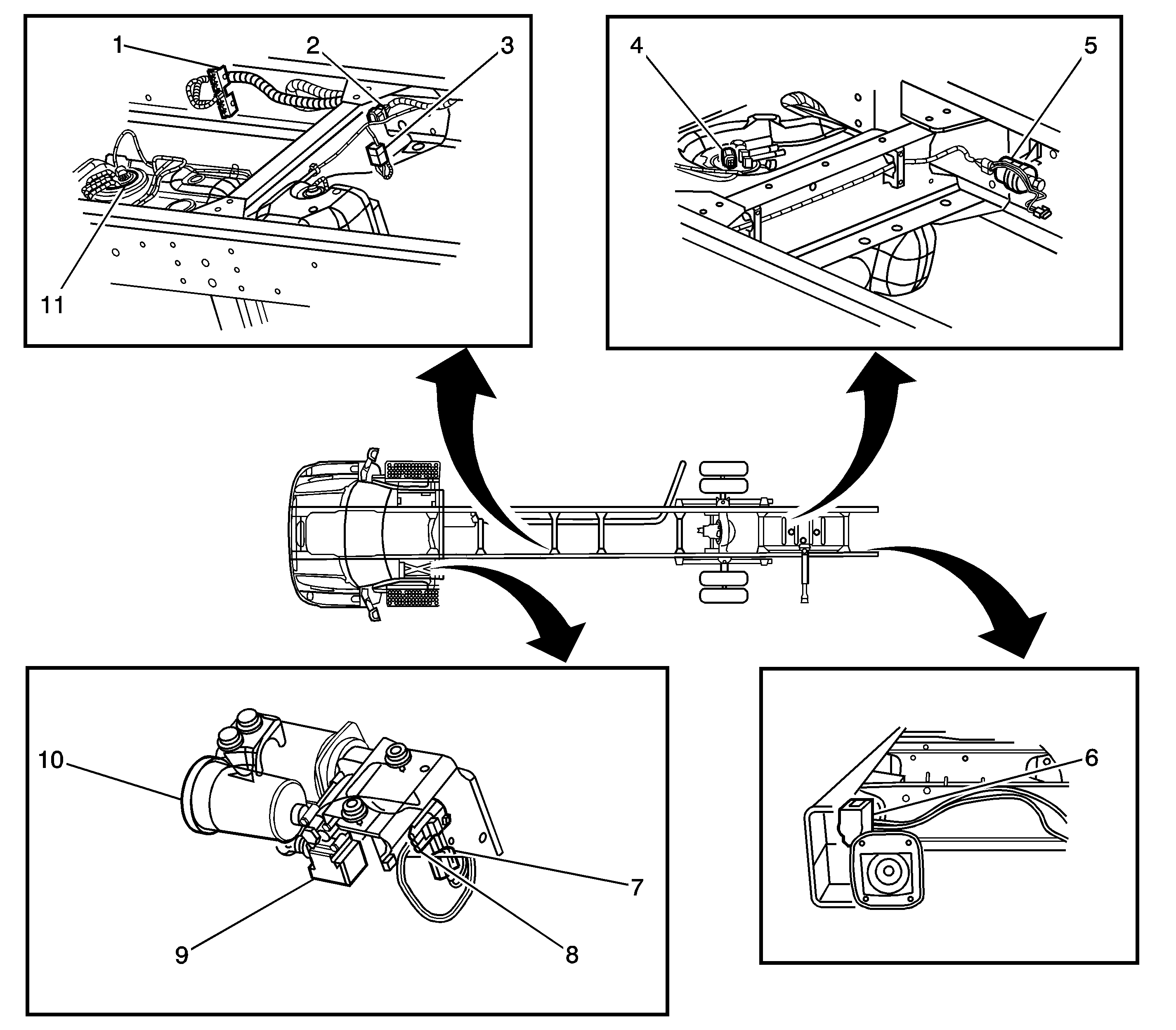

Object Number: 1014827  Size: LF
(1)Splice Pack SP400 (Ground Block)
(2)C409 (8 cavities) Fuel Tank Harness to the Chassis Harness
(3)Fuel Pump (FP) Relay
(4)Fuel Sender - Secondary
(5)Fuel Tank Transfer Pump - Secondary
(6)Trailer Connector (RQ2 and U86 or RQ3)
(7)C410 (3 cavities - K16) Chassis Harness to the Air Compressor Harness
(8)Air Compressor Connector (K16)
(9)Air Compressor Relay (K16)
(10)Air Compressor (K16)
(11)Fuel Sender - Primary