For 1990-2009 cars only
Auxiliary Air Tank Replacement 4500/5500
Removal Procedure
- Release air in the tank by pulling on the relief cable.
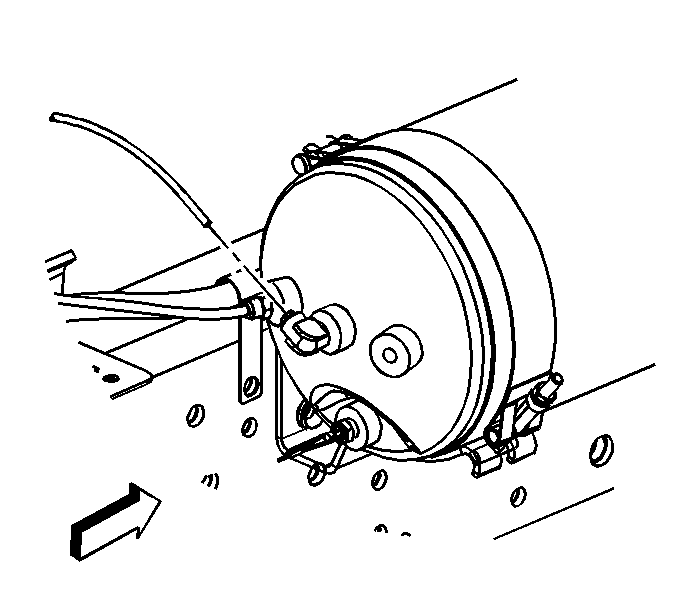
- Disconnect the pressure switch electrical connector.
- Disconnect the auxiliary air compressor inlet line at the reservoir.
- Disconnect the auxiliary air compressor outlet line at the reservoir.
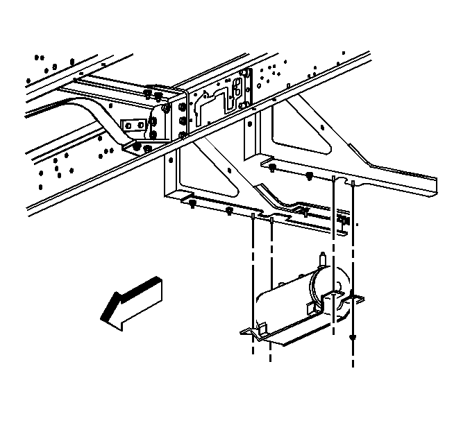
- Remove the auxiliary air compressor air tank mounting support nuts and the auxiliary air compressor air tank with the support.
- If required, remove the auxiliary air compressor air tank mounting strap nuts and remove the auxiliary air compressor air tank from the tank supports.
- If required, remove the pressure switch adapter, pressure switch, and assorted fittings from the air tank.

Installation Procedure
- If required, install the pressure switch adapter, pressure switch, and assorted fittings to the air tank.
- If required, install the auxiliary air compressor air tank onto the air support with 2 mounting straps and nuts.
- Install the auxiliary air compressor air tank with the support onto the step rail with the air tank support nuts.
- Connect the auxiliary air compressor outlet line at the reservoir.
- Connect the auxiliary air compressor inlet line at the reservoir.
- Connect the pressure switch electrical connector.
Notice: Refer to Fastener Notice in the Preface section.
Tighten
Tighten the air tank support strap nuts to 13 N·m (115 lb in).

Tighten
Tighten the air tank support nuts to 25 N·m (18 lb ft).
Auxiliary Air Tank Replacement 6500/7500/8500
Removal Procedure
- Remove the right side fuel tank. Refer to Fuel Tank Replacement .
- Release air in tank by pulling on the relief cable.
- Disconnect the pressure switch electrical connector.
- Disconnect the auxiliary air compressor inlet line at the reservoir.
- Disconnect the auxiliary air compressor outlet line at the reservoir.
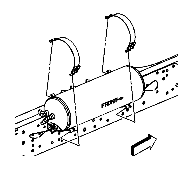
- Remove the auxiliary air compressor air tank mounting strap nuts.
- Remove the auxiliary air compressor air tank mounting straps and the auxiliary air compressor air tank from the mount.
- If required, remove the pressure switch adapter, pressure switch and assorted fittings from the air tank.


Installation Procedure
- If required, install the pressure switch adapter, pressure switch and assorted fittings to the air tank.
- Install the auxiliary air compressor air tank onto the tank mount with 2 mounting straps and nuts.
- Connect the auxiliary air compressor outlet line at the reservoir.
- Connect the auxiliary air compressor inlet line at the reservoir.
- Connect the pressure switch electrical connector.
- Install the right side fuel tank. Refer to Fuel Tank Replacement .
Notice: Refer to Fastener Notice in the Preface section.

Tighten
Tighten the air tank support strap nuts to 13 N·m (115 lb in).

