This vehicle is equipped with the DBC7 antilock braking system.
The vehicle is equipped with the following braking systems:
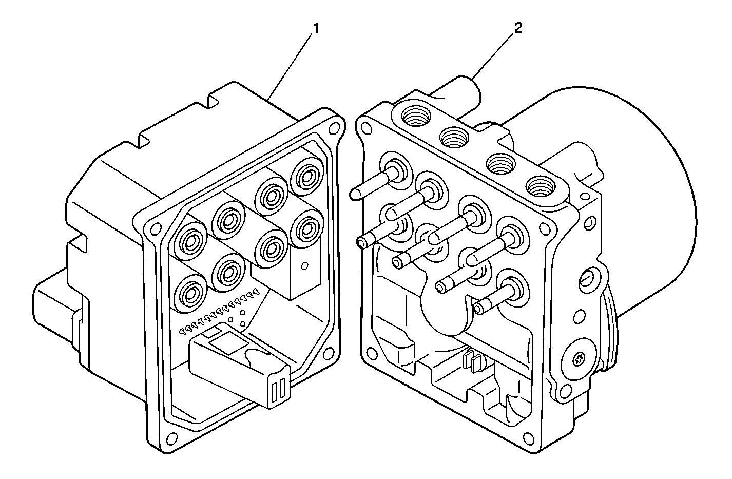
The following components are involved in the operation of the above systems:
The EBCM performs 1 initialization test each ignition cycle. The initialization of the EBCM occurs when 1 set of the following conditions occur:
Both of the following conditions occur:
OR
The initialization sequence may also be commanded with a scan tool.
The initialization sequence cycles each solenoid valve and the pump motor, as well as the necessary relays, for approximately 1.5 seconds to check component operation. The EBCM sets a DTC if any error is detected. The initialization sequence may be heard and felt while it is taking place, and is considered part of normal system operation.
The EBCM defines a drive cycle as the completion of the initialization sequence.
When wheel slip is detected during a brake application, the ABS enters antilock mode. During antilock braking, hydraulic pressure in the individual wheel circuits is controlled to prevent any wheel from slipping. A separate hydraulic line and specific solenoid valves are provided for each wheel. The ABS can decrease, hold, or increase hydraulic pressure to each wheel brake. The ABS cannot, however, increase hydraulic pressure above the amount which is transmitted by the master cylinder during braking.
During antilock braking, a series of rapid pulsations is felt in the brake pedal. These pulsations are caused by the rapid changes in position of the individual solenoid valves as the EBCM responds to wheel speed sensor inputs and attempts to prevent wheel slip. These pedal pulsations are present only during antilock braking and stop when normal braking is resumed or when the vehicle comes to a stop. A ticking or popping noise may also be heard as the solenoid valves cycle rapidly. During antilock braking on dry pavement, intermittent chirping noises may be heard as the tires approach slipping. These noises and pedal pulsations are considered normal during antilock operation.
Vehicles equipped with ABS may be stopped by applying normal force to the brake pedal. Brake pedal operation during normal braking is no different than that of previous non-ABS systems. Maintaining a constant force on the brake pedal provides the shortest stopping distance while maintaining vehicle stability.
The EBCM closes the inlet valve and keeps the outlet valve closed in order to isolate the system when wheel slip occurs. This holds the pressure steady on the brake so that the hydraulic pressure does not increase or decrease.
The EBCM decreases the pressure to individual wheels during a deceleration when wheel slip occurs. The inlet valve is closed and the outlet valve is opened. The excess fluid is stored in the accumulator until the return pump can return the fluid to the master cylinder.
The EBCM increases the pressure to individual wheels during a deceleration in order to reduce the speed of the wheel. The inlet valve is opened and the outlet valve is closed. The increased pressure is delivered from the master cylinder.
When drive wheel slip is noted while the brake is not applied, the EBCM will enter traction control mode.
First, the EBCM requests the PCM to reduce the amount of torque to the drive wheels via the requested torque signal circuit. The PCM reduces torque to the drive wheels by retarding spark timing and turning off fuel injectors. The PCM reports the amount torque delivered to the drive wheels via the delivered torque signal circuit.
If the engine torque reduction does not eliminate drive wheel slip, the EBCM will actively apply the drive wheel brakes. During traction control braking, hydraulic pressure in each drive wheel circuit is controlled to prevent the drive wheels from slipping. The master cylinder isolation valve closes in order to isolate the master cylinder from the rest of the hydraulic system. The prime valve then opens in order to allow the pump to accumulate brake fluid in order to build hydraulic pressure for braking. The drive wheel inlet and outlet solenoid valves then open and close in order to perform the following functions:
The IPC illuminates the ABS indicator when the following occurs:
The IPC illuminates the SERVICE TRACTION SYSTEM indicator in the message center when the electronic brake control module (EBCM) detects a malfunction in the traction control system. The IPC receives a class 2 message from the EBCM requesting illumination. The SERVICE TRACTION SYSTEM indicator illuminates for 60 seconds when the condition is present. The IPC sends a class 2 message to the radio in order to activate an audible warning.
The IPC illuminates the TRAC OFF indicator when the following occurs:
The IPC illuminates the TRACTION ACTIVE indicator in the message center when the electronic brake control module (EBCM) detects a traction control event. The IPC receives a class 2 message from the EBCM requesting illumination.