Tools Required
J 36660-A Torque Angle Meter
Removal Procedure
Notice: Modifications made to the engine or its individual components can effect the vehicle's emission controls and may cause the Malfunction Indicator Lamp (MIL), Check Engine, or Service Engine Soon lamp to illuminate. Modifications may also cause the vehicle to fail a required Emission Inspection/Maintenance test.
- Disconnect the negative battery cable. Refer to Battery Negative Cable Disconnection and Connection in Engine Electrical.
- Raise and support the vehicle. Refer to Lifting and Jacking the Vehicle in General Information.
- Drain the engine oil. Refer to Engine Oil and Oil Filter Replacement .
- Drain the cooling system. Refer to Cooling System Draining and Filling in Engine Cooling.
- Lower the vehicle.
- Remove the fuel injector sight shield. Refer to Fuel Injector Sight Shield Replacement .
- Disconnect the intake air temperature sensor (IAT) sensor.
- Remove the air inlet duct from the throttle body .
- Remove the ignition control module and bracket from the left cylinder head. Refer to Ignition Control Module Replacement in Engine Controls - 3.8L.
- Remove the right engine mount strut brackets. Refer to Engine Mount Strut Bracket Replacement - Right Upper .
- Remove the left engine mount strut bracket. Refer to Engine Mount Strut Bracket Replacement - Left Side
- Remove the left side spark plugs. Refer to Spark Plug Replacement in Engine Controls - 3.8L.
- Remove the lower intake manifold. Refer to Lower Intake Manifold Replacement .
- Remove the left exhaust manifold. Refer to Exhaust Manifold Replacement - Left Side .
- Remove the left valve rocker arm cover. Refer to Valve Rocker Arm Cover Replacement - Left Side .
- Remove the left rocker arms and push rods. Refer to Valve Rocker Arm and Push Rod Replacement .
- Remove the left cylinder head bolts. Discard the cylinder head bolts.
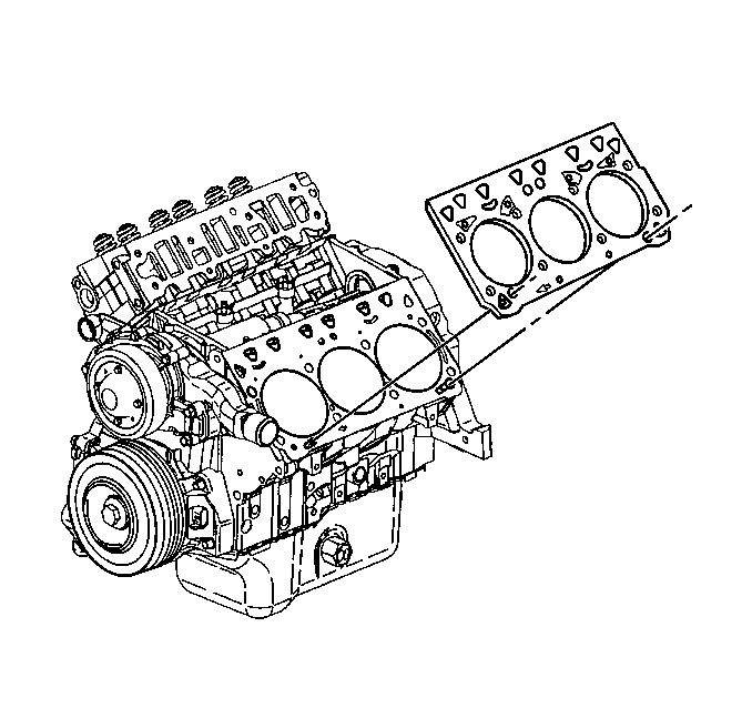
- Remove the left cylinder head.
- Remove the cylinder head gasket.
- Remove the caps, the springs, the valves, and the seals from the cylinder head. Refer to Cylinder Head Disassemble in Engine Mechanical - 3.8L Unit Repair.
- Clean the gasket mating surfaces on the cylinder head, the cylinder block and the intake manifold.
- Clean the cylinder block bolt hole threads.
- Inspect the engine block. Refer to Engine Block Cleaning and Inspection in Engine Mechanical - 3.8L Unit Repair.
- Inspect the cylinder head. Refer to Cylinder Head Cleaning and Inspection in Engine Mechanical - 3.8L Unit Repair.

Installation Procedure
- Install the springs, the caps, the seals, and the valves to the cylinder head. Refer to Cylinder Head Assemble in Engine Mechanical - 3.8L Unit Repair.
- Position the head gasket with the arrow pointing to the front of the engine.
- Install the left cylinder head.
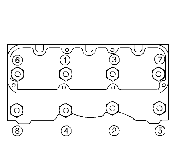
- Install the new cylinder head bolts (1-8).
- Tighten the cylinder head bolts (1-8) in the following sequence to 50 N·m (37 lb ft).
- Use the J 36660-A to rotate the cylinder head bolts (1-8) an additional 120 degrees.
- Install the left push rods and rocker arms. Refer to Valve Rocker Arm and Push Rod Replacement .
- Install the left valve rocker arm cover. Refer to Valve Rocker Arm Cover Replacement - Right Side .
- Install the left exhaust manifold. Refer to Exhaust Manifold Replacement - Left Side in Engine Exhaust.
- Install the lower intake manifold. Refer to Lower Intake Manifold Replacement .
- Install the left side spark plugs. Refer to Spark Plug Replacement in Engine Controls - 3.8L.
- Install the left engine mount strut bracket. Refer to Engine Mount Strut Bracket Replacement - Left Side .
- Install the right engine mount strut bracket. Refer to Engine Mount Strut Bracket Replacement - Right Upper .
- Install the ignition control module bracket and the ignition control module to the left cylinder head. Refer to Ignition Control Module Replacement in Engine Controls - 3.8L.
- Install the air inlet duct to the throttle body.
- Connect the intake air temperature (IAT) sensor electrical connector.
- Install the fuel injector sight shield. Refer to Fuel Injector Sight Shield Replacement .
- Fill the cooling system. Refer to Cooling System Draining and Filling in Engine Cooling.
- Fill the crankcase with engine oil. Refer to Engine Oil and Oil Filter Replacement .
- Connect the negative battery cable. Refer to Battery Negative Cable Disconnection and Connection in Engine Electrical.
- Inspect for leaks.
Notice: Head gaskets are not interchangeable. The head gasket must be installed with the arrow pointing to the front of the engine. Installing the head gasket in any other direction will cause gasket failure and possible engine failure.
Notice: This bolt is designed to permanently stretch when tightened, and therefore MUST be replaced anytime it is removed. The correct part number fastener must be used to replace this type of fastener. Do not use a bolt that is stronger in this application. If the correct bolt is not used, the parts will not be tightened correctly. The system or the components may be damaged.
Notice: This engine uses special torque to yield head bolts. This design bolt requires a special tightening procedure. Failure to follow the given procedure will cause head gasket failure and possible engine damage.
Notice: Use the correct fastener in the correct location. Replacement fasteners must be the correct part number for that application. Fasteners requiring replacement or fasteners requiring the use of thread locking compound or sealant are identified in the service procedure. Do not use paints, lubricants, or corrosion inhibitors on fasteners or fastener joint surfaces unless specified. These coatings affect fastener torque and joint clamping force and may damage the fastener. Use the correct tightening sequence and specifications when installing fasteners in order to avoid damage to parts and systems.
Tighten
