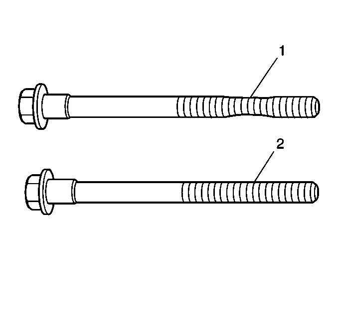
- Inspect the cylinder head gasket and mating surfaces for leaks,
corrosion and blow-by.
- If the gasket has failed, determine the cause. Gasket failure
may be caused by the following:
| • | Loose or warped cylinder head |
| • | Warped cylinder block surface |
| • | Missing, off location or not fully seated dowel pins |
| • | Corrosion in the seal area around the coolant passages |
| • | Chips or debris in the cylinder head bolt holes |
| • | Bolt holes in the cylinder block not drilled or tapped deep enough |
| • | Incorrect cylinder head bolt torque |
| • | Incorrect cylinder head bolt length |
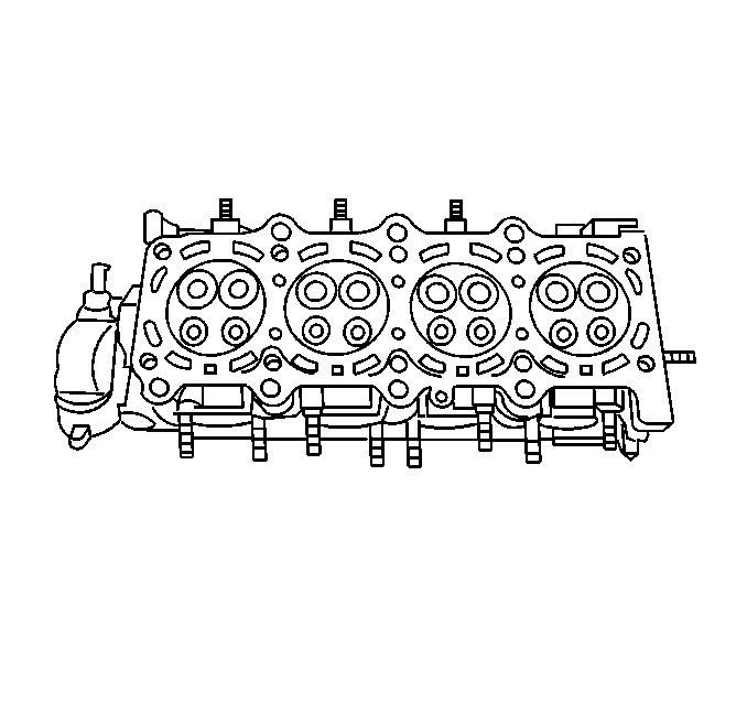
- Inspect the cylinder head
gasket surface.
| • | Cylinder head may be reused if corrosion is found only outside
a 4 mm (0.375 in) band around each combustion chamber. |
| • | Replace the cylinder head if the area between the valve seats
is cracked. |
| • | Replace the cylinder head if corrosion has been found inside a
4 mm (0.375 in) band around each combustion chamber. |
Important: Do not use a wire brush on any gasket sealing surface.
Do not attempt to weld the cylinder head, replace it.
- Clean the cylinder head. Remove all varnish, soot and carbon to the
bare metal.
- Clean the valve guides.
- Inspect the valve guides for wear.
- Inspect the valve seats for excessive wear and hot spots.
- Inspect the valve seating surfaces.
- Clean the threaded holes. Use a nylon bristle brush.
- Clean the remains of the sealer from the plug holes.
- Replace all suspect bolts.
- Inspect the cylinder head for cracks. Check between the valve
seats and in the exhaust ports.
- Inspect the cylinder head deck for corrosion, sand inclusions
and blow holes.
- Inspect all the threaded holes for damage. Threads may be reconditioned
with thread inserts.
- Inspect the intake, the exhaust and the cylinder head deck sealing
surfaces.
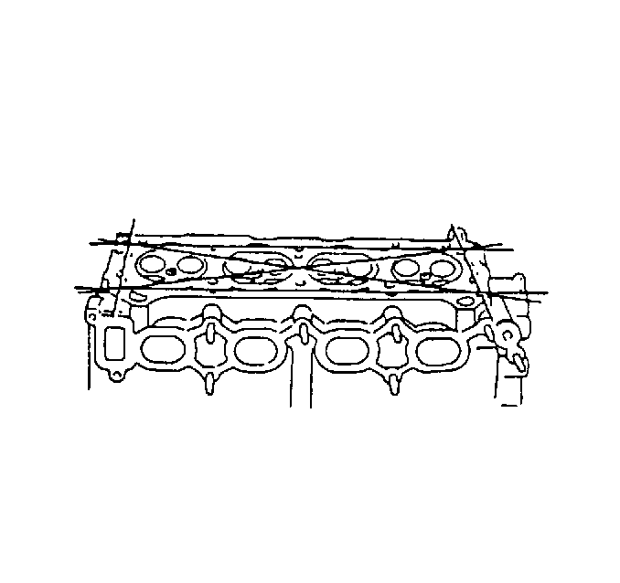
- Inspect the cylinder head
deck surface for flatness.
Maximum Cylinder Head Deck Warpage
0.05 mm (0.002 in)
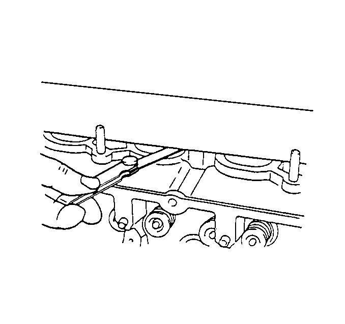
- Inspect the cylinder head
intake surface for flatness.
Maximum Cylinder Head Intake Surface Warpage
0.10 mm (0.004 in)
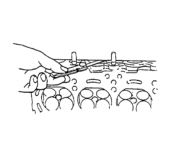
- Inspect the cylinder head
exhaust surface for flatness.
Maximum Cylinder Head Exhaust Surface Warpage
0.10 mm (0.004 in)
- If the warpage is greater than the maximum in any of the above
measurements, replace the cylinder head.
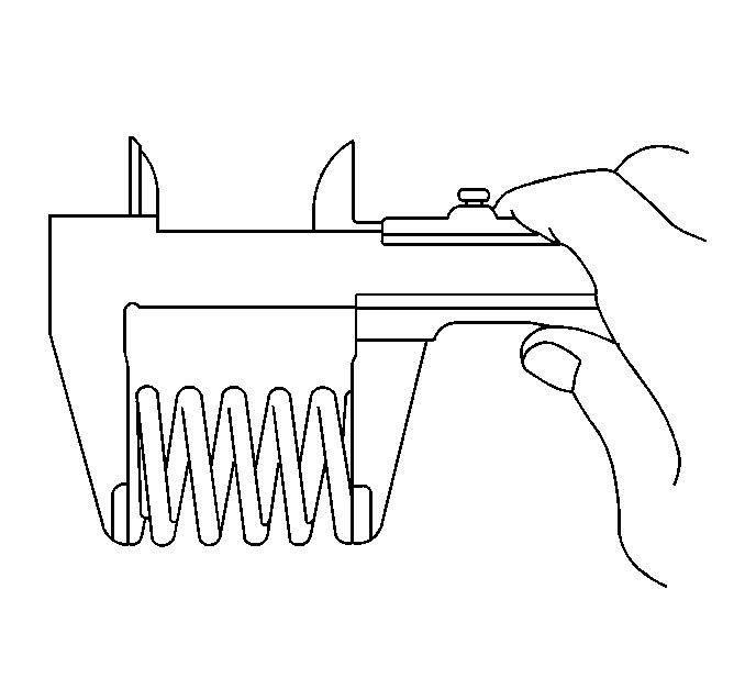
- Measure the free length
of each valve spring using a Vernier caliper.
Standard Inner Valve Spring Free Length
36.08 mm (1.4204 in)
Minimum Inner Valve Spring Free Length
35.00 mm (1.3780 in)
Standard Outer Valve Spring Free Length
40.44 mm (1.5921 in)
Minimum Outer Valve Spring Free Length
39.22 mm (1.5441 in)
- If the free length of any valve spring is not within specifications,
replace the valve spring.
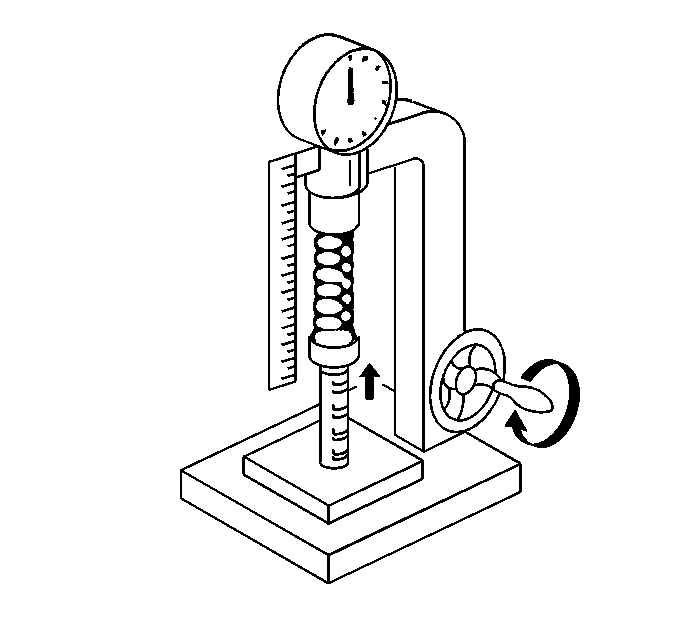
- Measure the tension of
the valve spring at the specified installed height using a spring tester.
Standard Inner Valve Spring Tension
6.9-7.9 kg (15.2-17.4 lb) at 27.5 mm
(1.08 in)
Minimum Inner Valve Spring Tension
5.9 kg (13.0 lb) at 27.5 mm (1.08 in)
Standard Outer Valve Spring Tension
15.4-17.8 kg (33.9-39.2 lb) at 31.7 mm
(1.25 in)
Minimum Outer Valve Spring Tension
13.3 kg (30.0 lb) at 31.7 mm (1.25 in)
- If the installed tension of any valve spring is not within specifications,
replace the valve spring.
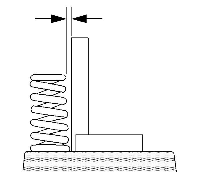
- Measure the valve spring
squareness deviation using a steel square.
Inner Valve Spring Squareness Deviation
1.6 mm (0.063 in)
Outer Valve Spring Squarness Deviation
1.8 mm (0.070 in)
- If the deviation of any valve spring is greater than the specified
maximum, replace the valve spring.
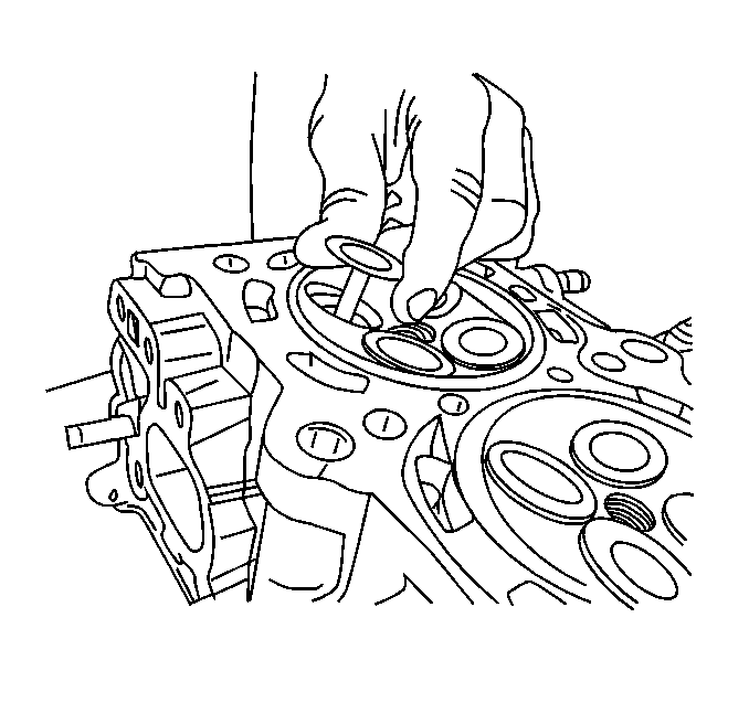
- Inspect the valve spring
seating surface of the valve spring seats for wear or gouging. Replace as
required.
- Temporarily install the valves into the cylinder head.
- Measure valve runout, valve face-to-valve seat contact pattern,
by performing the following:
| 28.1. | Apply a light coating of Prussian blue to the entire valve face.
Seat the valve but do not rotate it. The Prussian blue traces transferred
to the valve seat are an indication of concentricity of the valve seat. |
| 28.2. | Clean all traces of Prussian blue. |
| 28.3. | Apply a light coating of Prussian blue to the valve seat and repeat
the check. The traces of Prussian blue transferred to the valve face indicates
valve face concentricity. |


