For 1990-2009 cars only
- Coat the piston pin with engine oil.
- Align the connecting rod with the piston.
- Push the piston pin through the connecting rod and the piston bore by hand.
- Install new snap rings using a small screwdriver. Do not gouge the piston (1) when installing the snap rings.
- Ensure that the piston pin snap ring end gap is not aligned with the pin hole cutout portion of the piston.
- Lubricate the piston ring grooves and the piston rings with engine oil.
- Install the oil control expander ring.
- Install the lower oil control ring.
- Install the upper oil control ring.
- The lower and upper compression rings differ from each other in thickness, shape and cylinder wall contact surface color. The lower ring (2) is marked R and the upper ring is marked RN.
- Install the upper compression ring (1) (top ring) with the manufacturer's mark facing up.
- The piston ring end gaps must be staggered in order to provide an effective compression seal. After the rings are installed distribute their end gaps as follows:
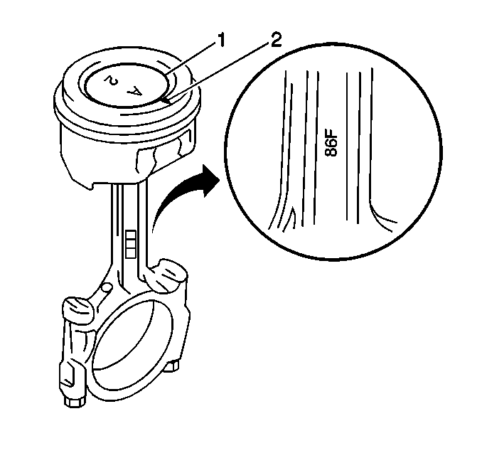
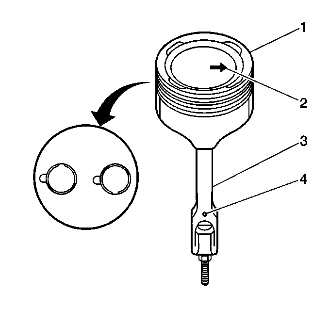
Important: Install the piston onto the connecting rod with the mark and the arrow (2) oriented toward the front of the engine.
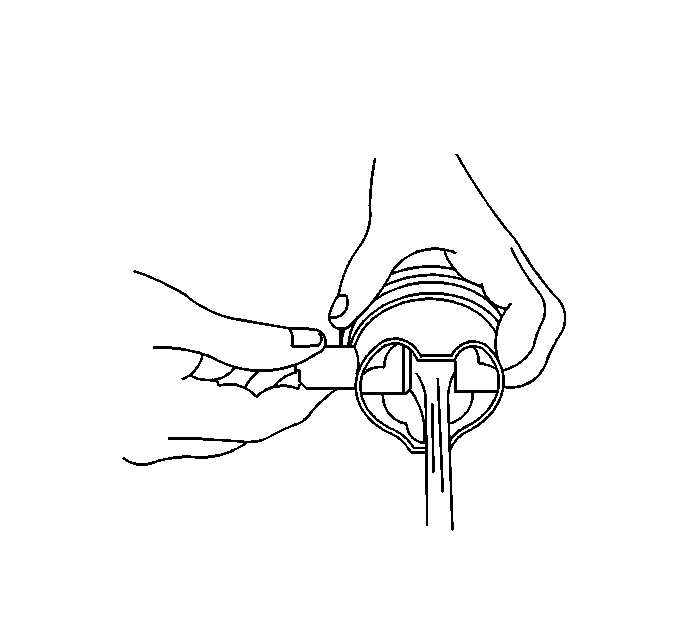
Important: The piston pin snap ring end gap should not be aligned with the pin hole cutout portion of the piston.
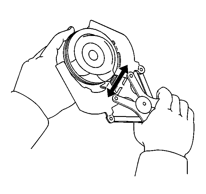
Notice: Use a piston ring expander to install the piston rings. The rings may be damaged if expanded more than necessary.
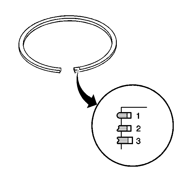
Install the lower compression ring (2), second ring with the manufacturer's mark facing up.
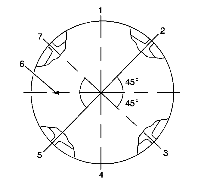
| 12.1. | Place the oil ring expander end gap (5) 45 degrees from the front of the piston (6) on the exhaust side of the engine. |
| 12.2. | Place the upper oil ring end gap (7) 45 degrees from the front of the piston (6) on the intake side of the engine. |
| 12.3. | Place the lower oil ring end gap (3) 180 degrees from the upper oil control ring end gap. |
| 12.4. | Place the lower compression ring end gap (5) 45 degrees from the front of the piston (6) on the exhaust side of the engine. |
| 12.5. | Place the upper compression ring end gap (2) 180 degrees from the lower compression ring end gap. |
