For 1990-2009 cars only
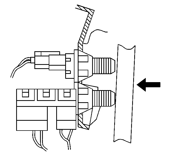
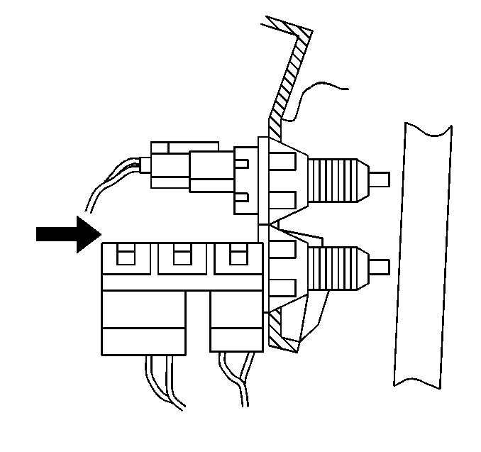
- Remove the left side insulator panel. Refer to Instrument Panel Insulator Replacement knee bolster panel.
- Press the brake pedal fully.
- Push the switches into the retainers until the switches are fully seated.
- Pull the brake pedal rearward against the pedal stop until the audible clicks can no longer be heard.
- The following brake pedal travel distances can be used to validate the proper cruise control release switch and stop lamp switch adjustment.
- Install the left side insulator panel. Refer to Instrument Panel Insulator Replacement .
Important: The cruise control release switch and the stop lamp switch are adjusted together. Incorrect adjustment of either of these switches may cause premature brake lining wear or the cruise control system to not work properly.


Cruise control release switch and the stop lamp switch contacts must actuate at 3.5 to 12.5 mm (1/8 to 1/2 in) of the brake pedal travel measured at the centerline of the brake pedal pad. Nominal actuation of the stop lamp switch contacts is about 4.5 mm (3/16 in) after the cruse control release switch actuation.
