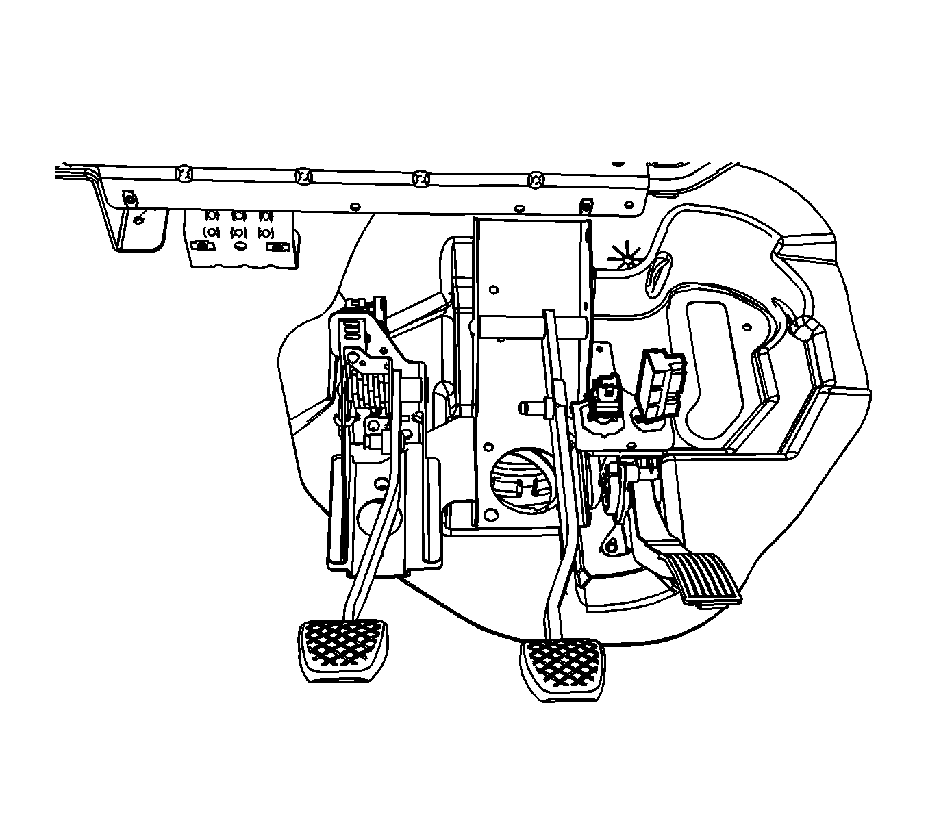
Brake Pedal Assembly Replacement Automatic Transaxle
Important: A new brake pedal assembly includes a disposable switch adjustment shim on the stop lamp switch contact area. Use this shim for switch adjustment as instructed, then remove and discard the shims.
Removal Procedure
- Remove the instrument panel (I/P) sound insulator. Refer to Instrument Panel Insulator Replacement .
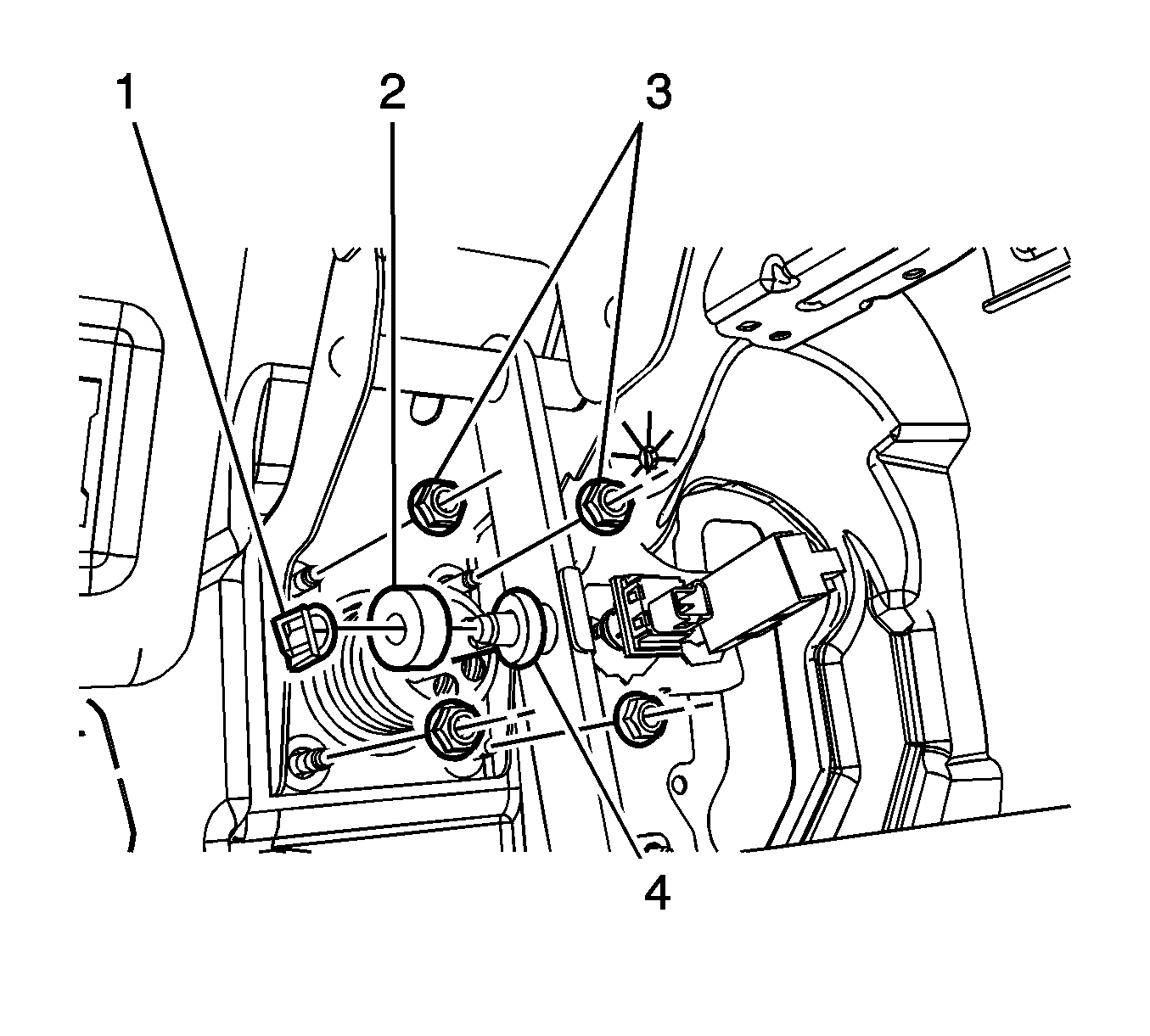
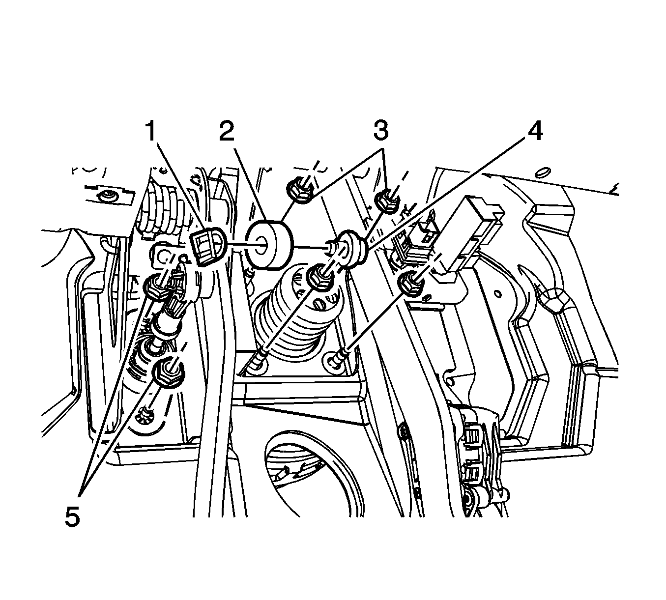
- Remove the brake booster pushrod retaining clip (1) and bushing (2).
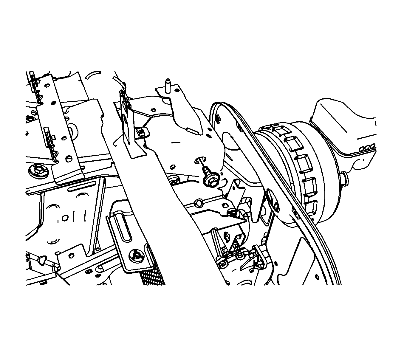
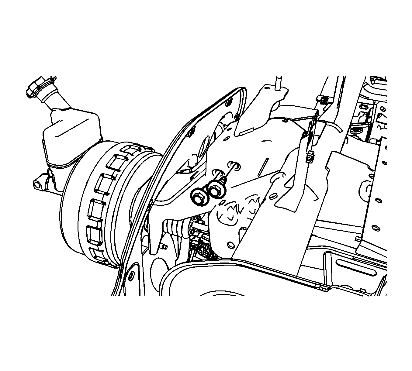
- Loosen the 4 brake booster mounting nuts (3).
- Release the brake booster pushrod (4) from the brake pedal pivot pin.
- Remove the 4 brake booster mounting nuts.
- Remove the RH upper brake pedal bracket-to-steering column bracket bolt.
- Remove the 2 LH upper brake pedal bracket-to-steering column bolts.
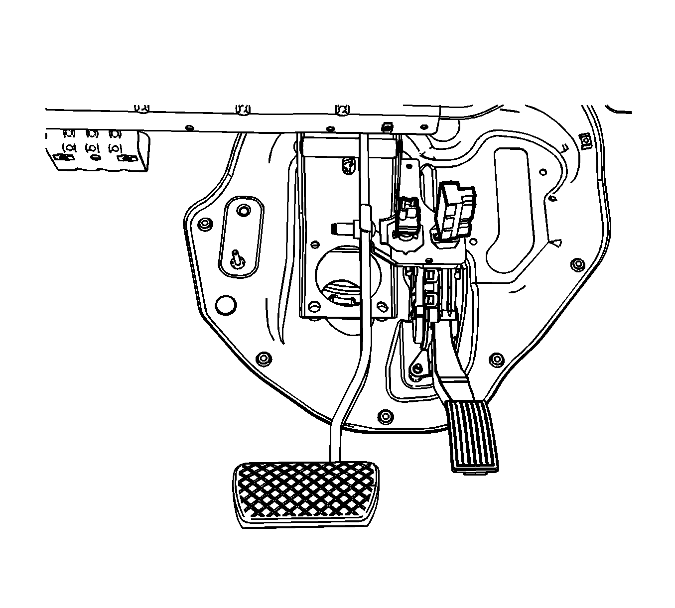
- Lower the brake pedal assembly to access the stop lamp and cruise release switches.
- Remove the stop lamp switch. Refer to Stop Lamp Switch Replacement .
- Remove the cruise release switch. Refer to Cruise Control Release Switch Replacement .
- Remove the brake pedal assembly.
Installation Procedure
- Install the brake pedal assembly to the vehicle.
- Install the cruise release switch to the pedal bracket. Refer to Cruise Control Release Switch Replacement .
- Install the stop lamp switch to the pedal bracket. Refer to Stop Lamp Switch Replacement .
- Move the brake pedal assembly to the installed position.
- Loosely install the 2 LH upper brake pedal bracket-to-steering column bracket bolts.
- Loosely install the RH upper brake pedal bracket-to-steering column bolt.
- Loosely install the 4 brake booster mounting nuts (3).
- Apply a thin coating of high temperature grease GM P/N 12345996 (Canadian P/N 10953501) to the pushrod pin on the brake pedal.
- Connect the brake booster pushrod (4) to the brake pedal pivot pin.
- Install the bushing (2) and retaining clip (1) to the brake pedal.
- Tighten the vacuum brake booster mounting nuts.
- Tighten the LH and RH upper brake pedal bracket-to-steering column bolts.
- Adjust the stop lamp switch. Refer to Stop Lamp Switch Adjustment .
- Adjust the cruise control release switch. Refer to Cruise Release Switch Adjustment .
- Install the I/P sound insulator. Refer to Instrument Panel Insulator Replacement .
Notice: Refer to Fastener Notice in the Preface section.
Tighten
Tighten the nuts to 22 N·m (16 lb ft).
Tighten
Tighten the nuts to 25 N·m (18 lb ft).
Brake Pedal Assembly Replacement Manual Transaxle
Important:
• The brake pedal and clutch pedal are serviced as an assembly. • A new brake and clutch pedal assembly includes disposable switch adjustment shims on the clutch arm switch contact areas and on the stop lamp switch contact area. Use these shims for switch adjustment as instructed then remove and discard the shims.
Removal Procedure
- Remove the instrument panel (I/P) sound insulator. Refer to Instrument Panel Insulator Replacement .
- Remove the intermediate steering shaft. Refer to Intermediate Steering Shaft Replacement .
- Remove the brake booster pushrod retaining clip (1) and bushing (2).
- Loosen the 4 brake booster mounting nuts (3).
- Loosen the 2 clutch pedal bracket mounting nuts (4).
- Release the clutch master cylinder pushrod from the clutch pedal pivot pin.
- Release the brake booster pushrod (5) from the brake pedal pivot pin.
- Remove the 4 brake booster mounting nuts.
- Remove the 2 clutch pedal bracket mounting nuts.
- Remove the RH upper brake pedal bracket-to-steering column bracket bolt.
- Remove the 2 LH upper brake pedal bracket-to-steering column bolts.
- Lower the brake pedal assembly to access the brake pedal and clutch pedal switches.
- Remove the stop lamp switch. Refer to Stop Lamp Switch Replacement .
- Remove the cruise release switch. Refer to Cruise Control Release Switch Replacement .
- Remove the clutch pedal position switch from the pedal bracket. Refer to Clutch Pedal Position Switch Replacement .
- Remove the clutch pedal engine start switch from the pedal bracket. Refer to Clutch Pedal Engine Start Switch Replacement .
- Remove the brake pedal and clutch pedal assembly.
Installation Procedure
- Install the brake pedal and clutch pedal assembly to the vehicle.
- Install the cruise release switch to the pedal bracket. Refer to Cruise Control Release Switch Replacement .
- Install the stop lamp switch to the pedal bracket. Refer to Stop Lamp Switch Replacement .
- Install the clutch pedal engine start switch to the pedal bracket. Refer to Clutch Pedal Engine Start Switch Replacement .
- Install the clutch pedal position switch to the pedal bracket. Refer to Clutch Pedal Position Switch Replacement .
- Move the brake pedal assembly to the installed position.
- Loosely install the 2 LH upper brake pedal bracket-to-steering column bracket bolts.
- Loosely install the RH upper brake pedal bracket-to-steering column bolt.
- Loosely install the 4 brake booster mounting nuts (3).
- Apply a thin coating of high temperature grease GM P/N 12345996 (Canadian P/N 10953501) to the pushrod pin on the brake pedal and to the pushrod pin on the clutch pedal.
- Connect the brake booster pushrod (5) to the brake pedal pivot pin.
- Install the bushing (2) and retaining clip (1) to the brake pedal.
- Loosely install the 2 clutch pedal bracket mounting nuts (4).
- Secure the clutch master cylinder pushrod to the clutch pedal pivot pin.
- Tighten the vacuum brake booster mounting nuts.
- Tighten the clutch pedal bracket mounting nuts.
- Tighten the LH and RH upper brake pedal bracket-to-steering column bolts.
- Install the intermediate steering shaft. Refer to Intermediate Steering Shaft Replacement .
- Adjust the stop lamp switch. Refer to Stop Lamp Switch Adjustment .
- Adjust the cruise control release switch. Refer to Cruise Release Switch Adjustment .
- Adjust the clutch pedal position switch. Refer to Clutch Pedal Position Switch Adjustment .
- Adjust the clutch pedal engine start switch. Refer to Clutch Pedal Engine Start Switch Replacement .
- Install the I/P sound insulator. Refer to Instrument Panel Insulator Replacement .
Notice: Refer to Fastener Notice in the Preface section.
Tighten
Tighten the nuts to 22 N·m (16 lb ft).
Tighten
Tighten the nuts to 10 N·m (89 lb in).
Tighten
Tighten the nuts to 25 N·m (18 lb ft).
