For 1990-2009 cars only
Removal Procedure
- Place the steering wheel in the straight forward position.
- Remove the knee bolster. Refer to Knee Bolster Replacement.
- Remove the knee bolster reinforcement. Refer to Driver Knee Bolster Reinforcement Replacement.
- Remove the steering wheel. Refer to Steering Wheel Replacement.
- Remove the steering column trim covers. Refer to Steering Column Trim Cover Replacement.
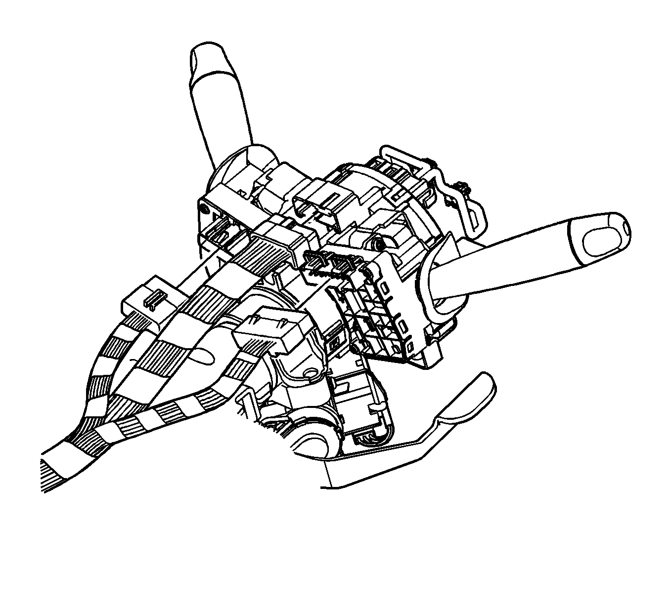
- Disconnect the head lamp/turn signal harness connector from the SIR coil module assembly.
- Disconnect the wiper/washer harness connector from the SIR coil module assembly.
- Disconnect the SIR coil harness connector from the SIR coil module assembly.
- Remove the SIR coil module assembly. Refer to Steering Wheel Inflatable Restraint Module Coil Replacement.
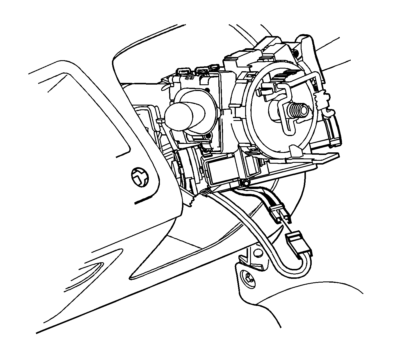
- Disconnect the ignition lock cylinder harness connector.
- Disconnect the ignition switch harness connector.
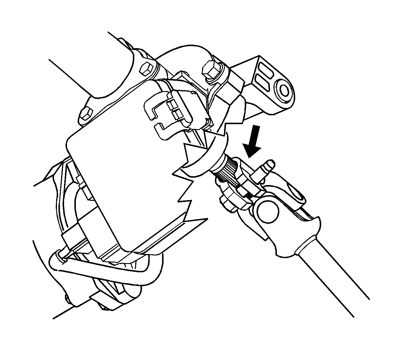
- Place scribe marks on the intermediate steering shaft and on the steering column shaft.
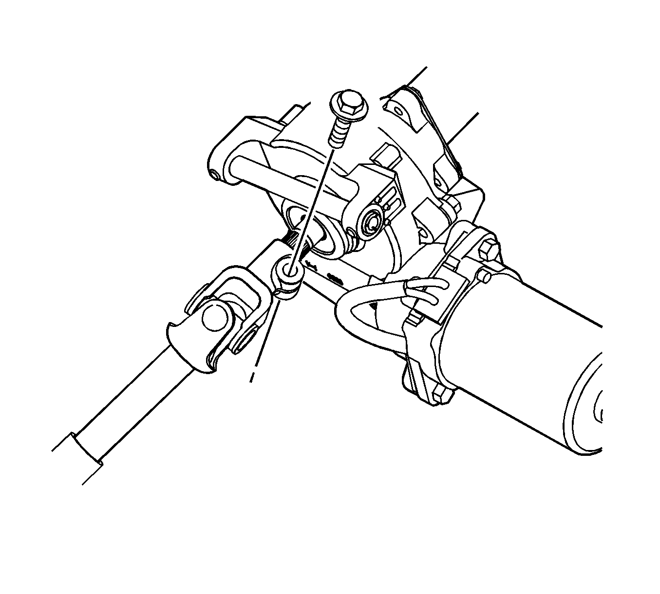
- Remove the intermediate shaft pinch bolt at the steering column and discard the bolt.
- Slide the intermediate shaft off of the steering column.
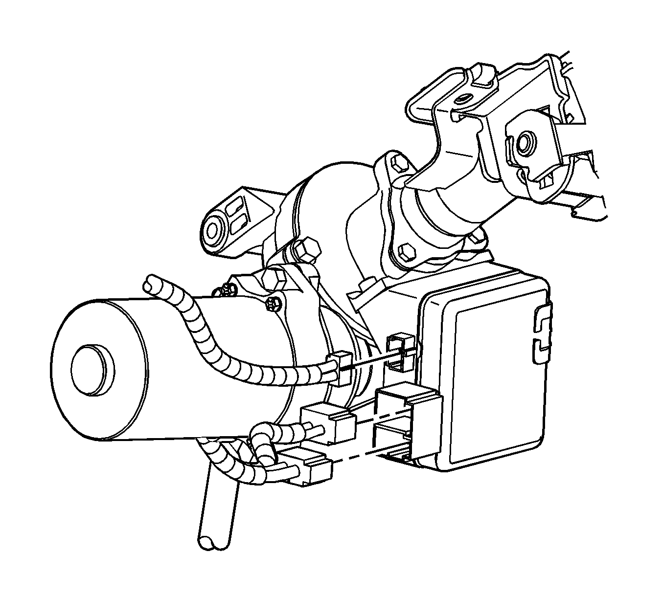
- Disconnect the electric power steering (EPS) control module power feed harness connector.
- Disconnect the EPS control module small harness connector.
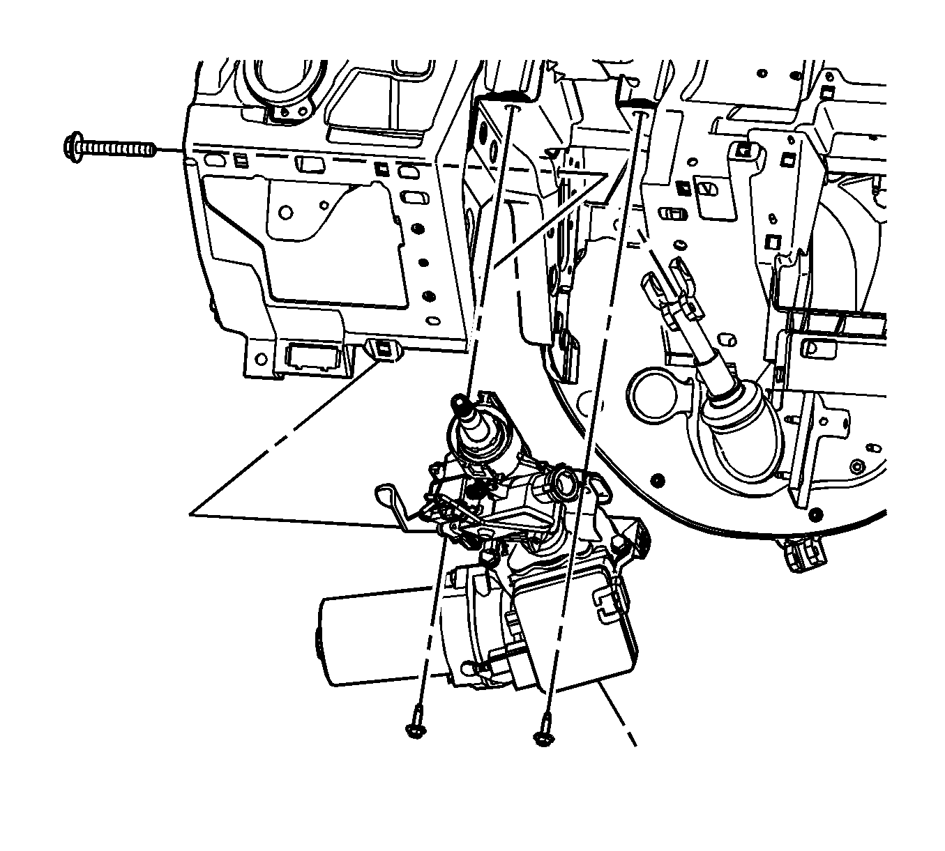
- Remove the steering column pivot bolt.
- Remove the steering column mounting bolts.
- Remove the column from the vehicle and place the column on a bench.
- Remove the ignition lock cylinder case from the steering column. Refer to Ignition Lock Cylinder Case Replacement.
Important: Ensure the front wheels are in the straight ahead position and the steering wheel is centered in order to mark the intermediate steering shaft position properly.
Installation Procedure
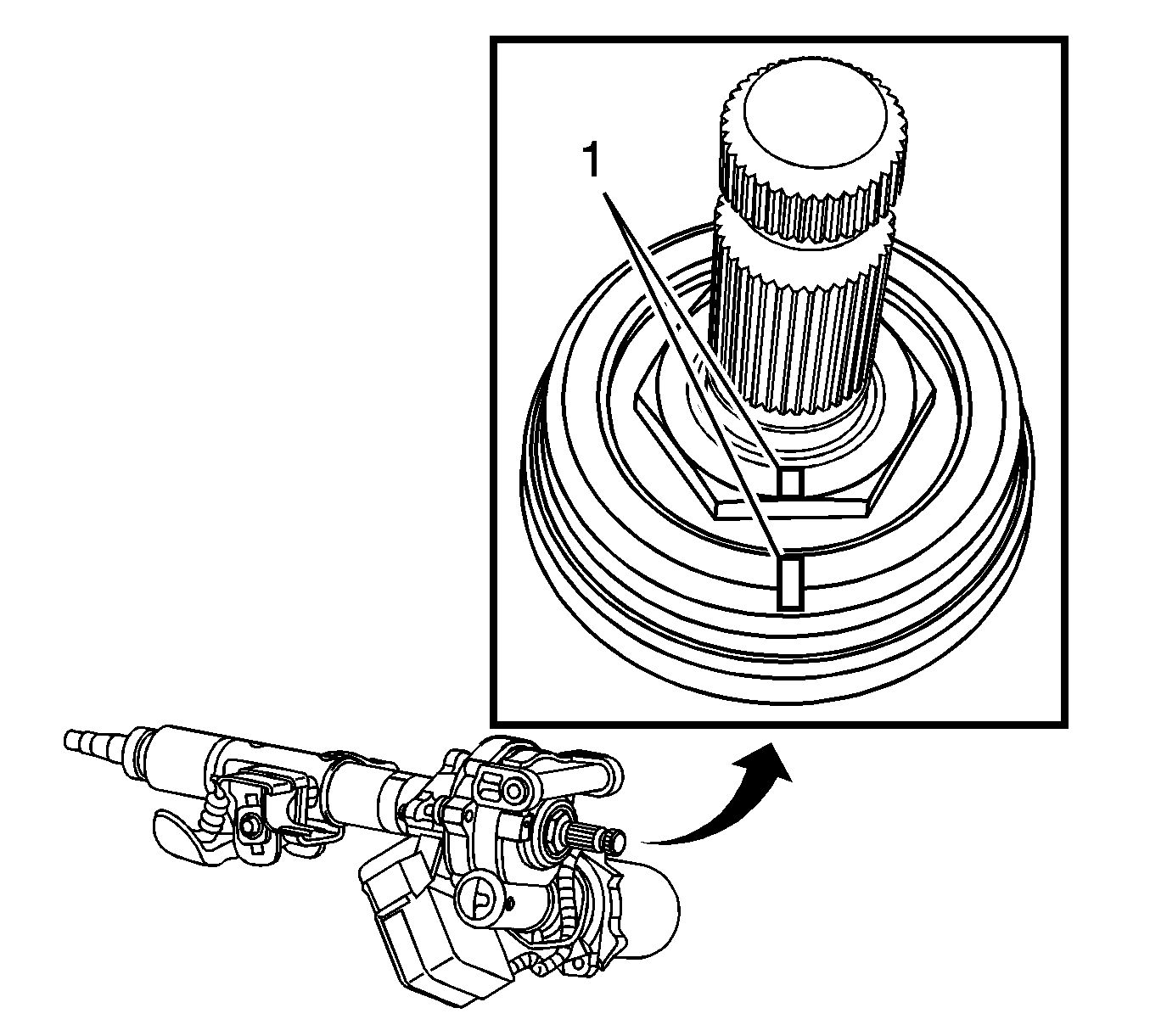
- If you are installing a NEW steering column, align the manufacturer match marks (1) on the lower shaft.
- If you are installing a NEW steering column, copy the scribe marks from the old column to the new column.
- Install the ignition lock cylinder case to the steering column. Refer to Ignition Lock Cylinder Case Replacement.
- Position the steering column in the vehicle.
- Hand start the steering column mid-pivot bolt.
- Hand start the steering column mounting bolts.
- Tighten the column bolts using the following order:
- Tighten the mid-pivot bolt to 25 N·m (18 lb ft).
- Tighten the right side column mounting bolt to 25 N·m (18 lb ft).
- Tighten the left side column mounting bolt to 25 N·m (18 lb ft).
- Connect the EPS control module power feed harness connector.
- Connect the EPS control module small harness connector.
- Slide the intermediate shaft onto the steering column while aligning the previously scribed marks.
- Install a NEW intermediate steering shaft bolt.
- Connect the ignition lock cylinder harness connector.
- Connect the ignition switch harness connector.
- Install the SIR coil module assembly. Refer to Steering Wheel Inflatable Restraint Module Coil Replacement.
- Connect the SIR coil harness connector to the SIR coil module assembly.
- Connect the wiper/washer harness connector to the SIR coil module assembly.
- Connect the head lamp/turn signal harness connector to the SIR coil module assembly.
- Install the column trim covers. Refer to Steering Column Trim Cover Replacement.
- Install the knee bolster reinforcement. Refer to Driver Knee Bolster Reinforcement Replacement.
- Install the knee bolster. Refer to Knee Bolster Replacement.
- Install the steering wheel. Refer to Steering Wheel Replacement.
- If you installed a new theft deterrent module, program the theft deterrent module. Refer to Control Module References for programming and setup information.

Notice: Refer to Fastener Notice in the Preface section.
Tighten


Important: For proper realignment of the steering column to intermediate shaft, use the previously scribed marks.

Tighten
Tighten bolt to 34 N·m (25 lb ft).


