Special Tools
| • | J 8037 Piston Ring Compressor |
For equivalent regional tools, refer to
Special Tools.
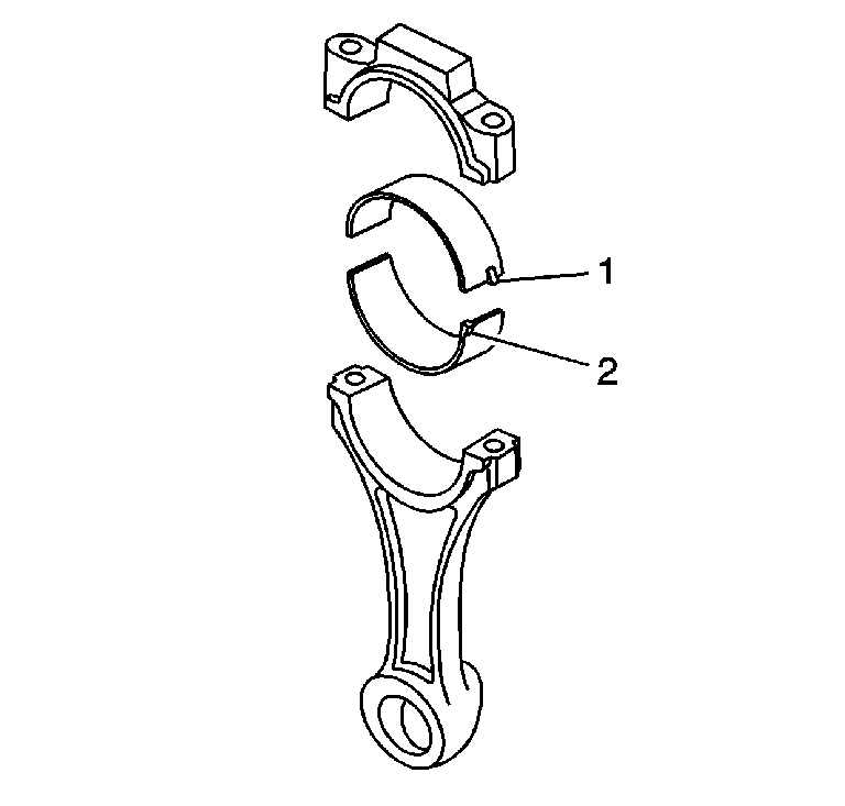
Note: The connecting rod bearing with the notch all the way out against the edge of the bearing (2) is the connecting rod bearing. The connecting rod bearing with the notch "in board" (1) is the connecting rod cap bearing.
- Select the connecting rod bearing according to the
Connecting Rod Bearings Selection Specifications chart.
- Position the crankshaft so the connecting rod journal is opposite the piston and connecting rod assembly being installed.
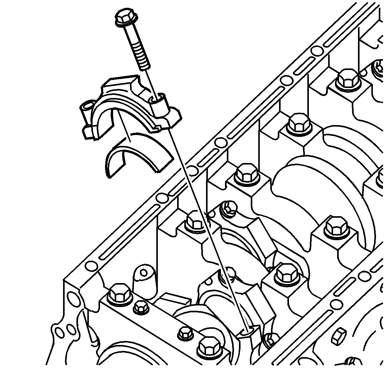
- Install the connecting rod bearing inserts.
- Lubricate the cylinder wall and piston rings with engine oil.
- Install the
J 8037 compressor
to the piston to compress the piston rings.
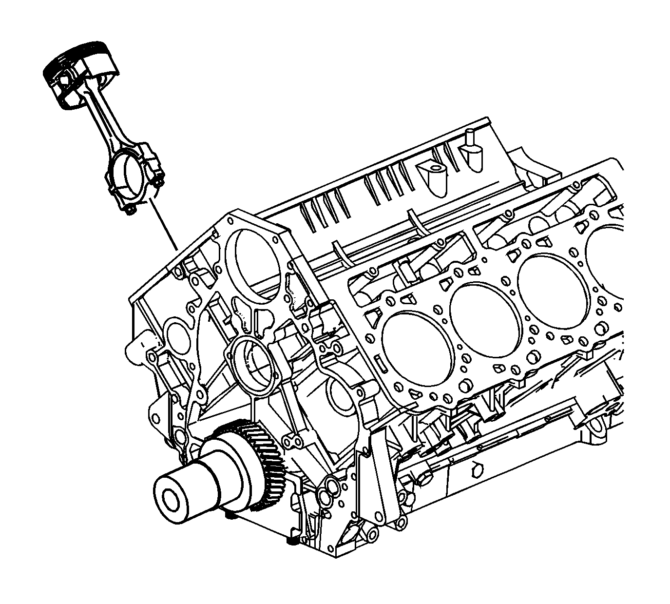
- Orientate the piston front mark and the piston inside mark to the engine block.
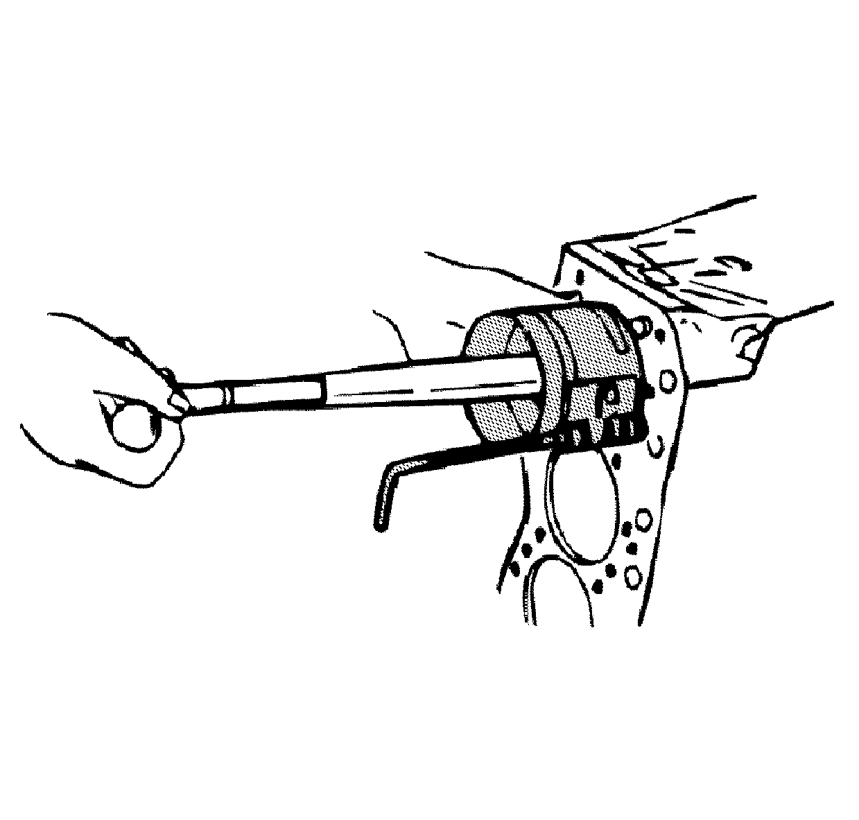
Caution: The chamfered side of the connecting rod large journal ends must face away from each other on a common crankshaft journal. Placement of the chamfered side of the connecting rod large journal ends
in any other direction or combination will cause damage to the crankshaft, connecting rod and connecting rod bearing.
- Push the piston and connecting rod assembly into the engine.
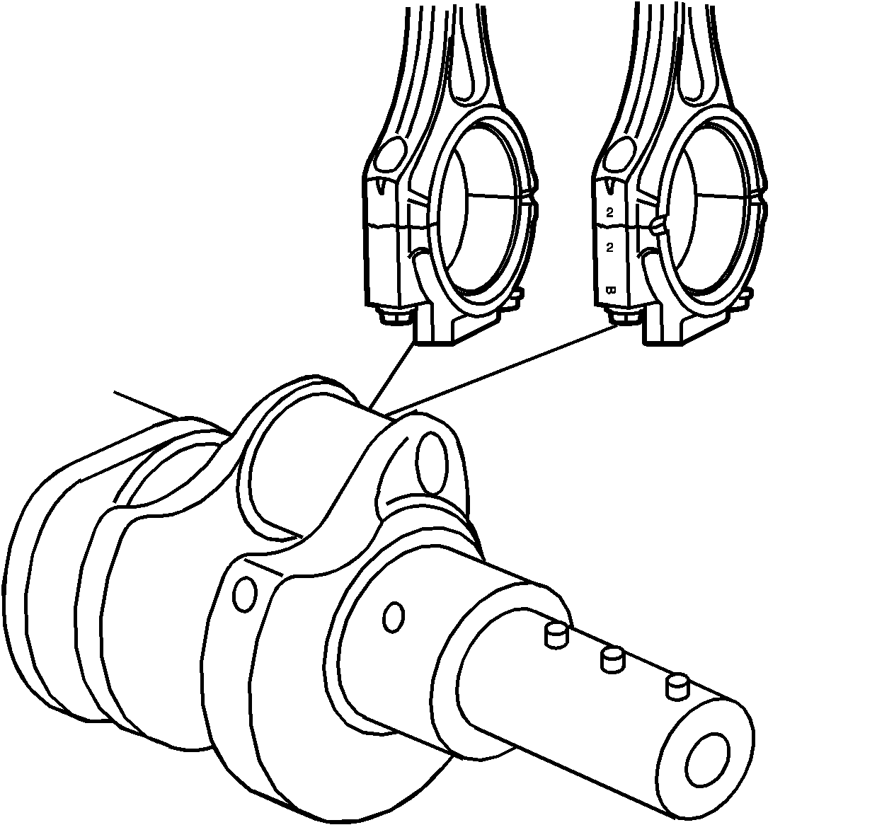
- Install the gauging plastic onto the connecting rod journal. Install the gauging plastic the full width of the journal.
- Install the connecting rod cap with its stamped cylinder number aligned with the stamped cylinder number on the connecting rod.
Caution: Refer to Fastener Caution in the Preface section.
- Install the original connecting rod cap bolts for the plastic gauging. NEW bolts will be used for final assembly.
- Tighten the bolts in three steps.
| 11.1. | 1st step
64 N·m (47 lb ft) |
| 11.2. | 2nd step
30 degrees using
J 45059 meter |
| 11.3. | 3rd step
30 degrees using
J 45059 meter |
- Remove the connecting rod cap bolts.
- Compare the width of the gauging plastic with the scale printed on the gauging plastic container. The connecting rod bearing clearance should be 0.10 mm (0.0039 in).
- Discard the original connecting rod bolts once the plastic gauging is completed. NEW connecting rod bolts will be used for final assembly.
- Carefully clean the gauging plastic from the bearing surface and the crankpin.
- Lubricate the connecting rod bearing inserts with engine oil.
- Install the connecting rod caps with the stamped cylinder number aligned with the stamped cylinder number on the connecting rods.
Caution: This component uses bolts with a preapplied molybdenum disulfide coating for thread lubrication. Do not remove the coating or use any additional lubricant. Improperly lubricated threads will
adversely affect the bolt torque and clamp load. Improper bolt torque and clamp load can lead to engine damage.
- Install NEW connecting rod cap bolts.
- Tighten the connecting rod cap bolts in three steps.
| 19.1. | 1st step
64 N·m (47 lb ft) |
| 19.2. | 2nd step
30 degrees using
J 45059 meter |
| 19.3. | 3rd step
30 degrees using
J 45059 meter |


