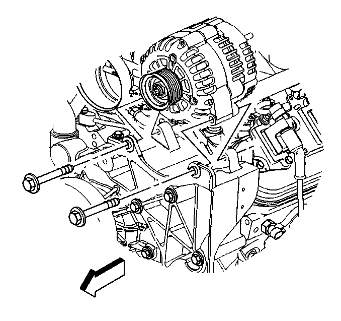
Generator Replacement 6.6L
Removal Procedure
Caution: Refer to Battery Disconnect Caution in the Preface section.
- Remove the upper fan shroud. Refer to Engine Coolant Fan Upper Shroud Replacement .
- Remove the drive belt. Refer to Drive Belt Replacement .
- Remove the generator bolts (1).
- Remove the generator front support bracket attached to the generator bracket and the generator.
- Reposition the generator to access wiring.
- Remove the positive battery cable nut from the generator.
- Disconnect the generator electrical connector.
- Remove the generator (2).
Installation Procedure
- Install the generator (2) to the generator bracket.
- Connect the generator electrical connector.
- Install the positive battery cable to the generator stud.
- Install the cable nut to the generator stud.
- Install the generator bolts (1).
- Install the generator front support bracket and attach it to the generator and the generator bracket.
- Install the drive belt. Refer to Drive Belt Replacement .
- Install the upper fan shroud. Refer to Engine Coolant Fan Upper Shroud Replacement .
Notice: Refer to Fastener Notice in the Preface section.
Tighten
Tighten the positive cable nut to 10 N·m (89 lb in).
Tighten
Tighten the generator bolts to 50 N·m (37 lb ft).
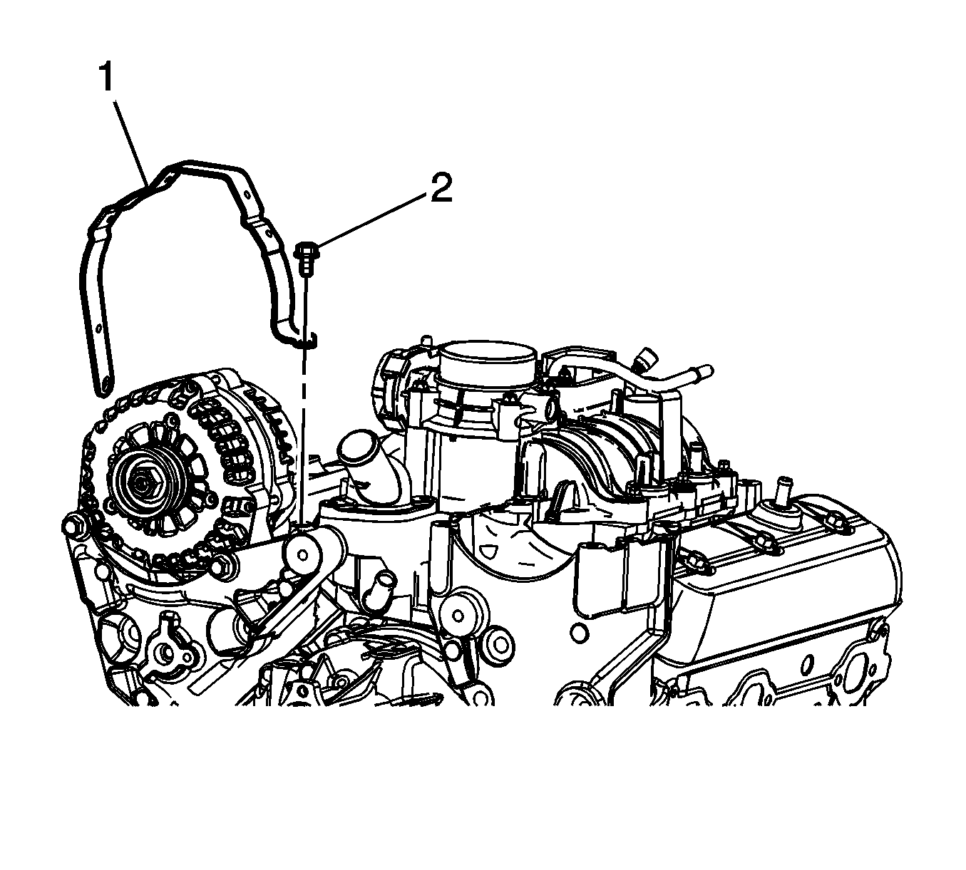
Generator Replacement 4.3L
Removal Procedure
- Disconnect the negative battery cable. Refer to Battery Negative Cable Disconnection and Connection .
- Remove the drive belt. Refer to Drive Belt Replacement .
- Unbolt and reposition the oil level indicator tube. Refer to Oil Level Indicator and Tube Replacement .
- Unbolt and reposition the oil fill tube. Refer to Oil Filler Tube Replacement .
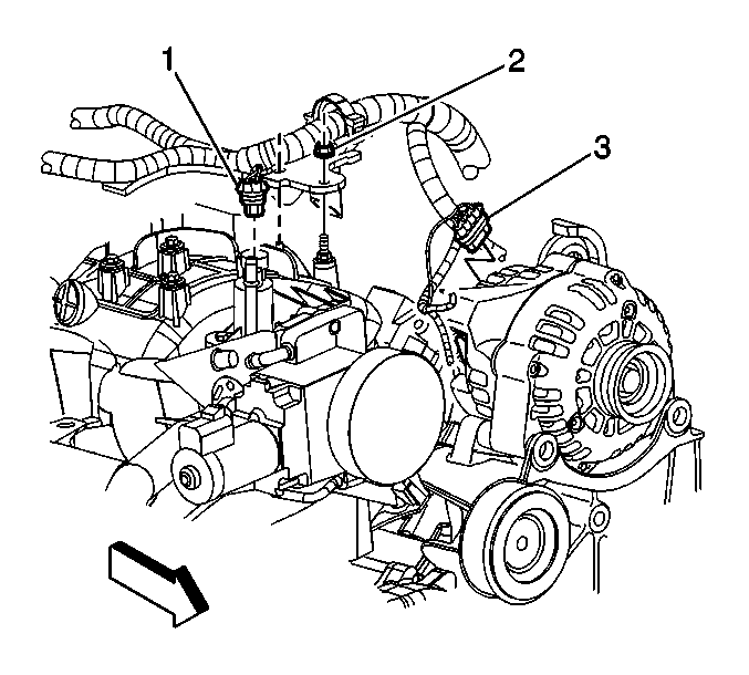
- Disconnect the engine wiring harness electrical connector (1) from the generator.
- Remove the oil fill tube bracket stud (2).
- Reposition the engine wiring harness clip.
- Reposition the positive battery cable boot (2) at the generator.
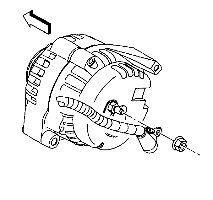
- Remove the generator nut (3).
- Remove the positive battery cable (1) from the generator.
- Remove the oil fill tube bracket bolt (2) and bracket (1).
- Remove the generator bolts (2) and generator (1).


Installation Procedure
- Install the generator (1) and bolts (2).
- Install the oil fill tube bracket (1) and bolt (2).
- Install the positive cable (1) to the generator.
- Install the generator nut (3).
- Position the positive cable boot (2) at the generator.
- Position the engine wiring harness clip to the generator bracket.
- Install the oil fill tube bracket stud (2).
- Connect the engine wiring harness electrical connector (1) to the generator.
- Position and install the oil fill tube. Refer to Oil Filler Tube Replacement .
- Position and install the oil level indicator tube. Refer to Oil Level Indicator and Tube Replacement .
- Install the drive belt. Refer to Drive Belt Replacement .
- Connect the negative battery cable. Refer to Battery Negative Cable Disconnection and Connection .
Notice: Refer to Fastener Notice in the Preface section.
Tighten
Tighten the bolts to 50 N·m (37 lb ft).
Tighten
Tighten the bolt to 25 N·m (18 lb ft).
Tighten
Tighten the nut to 10 N·m (89 lb in).
Tighten
Tighten the stud to 25 N·m (18 lb ft).
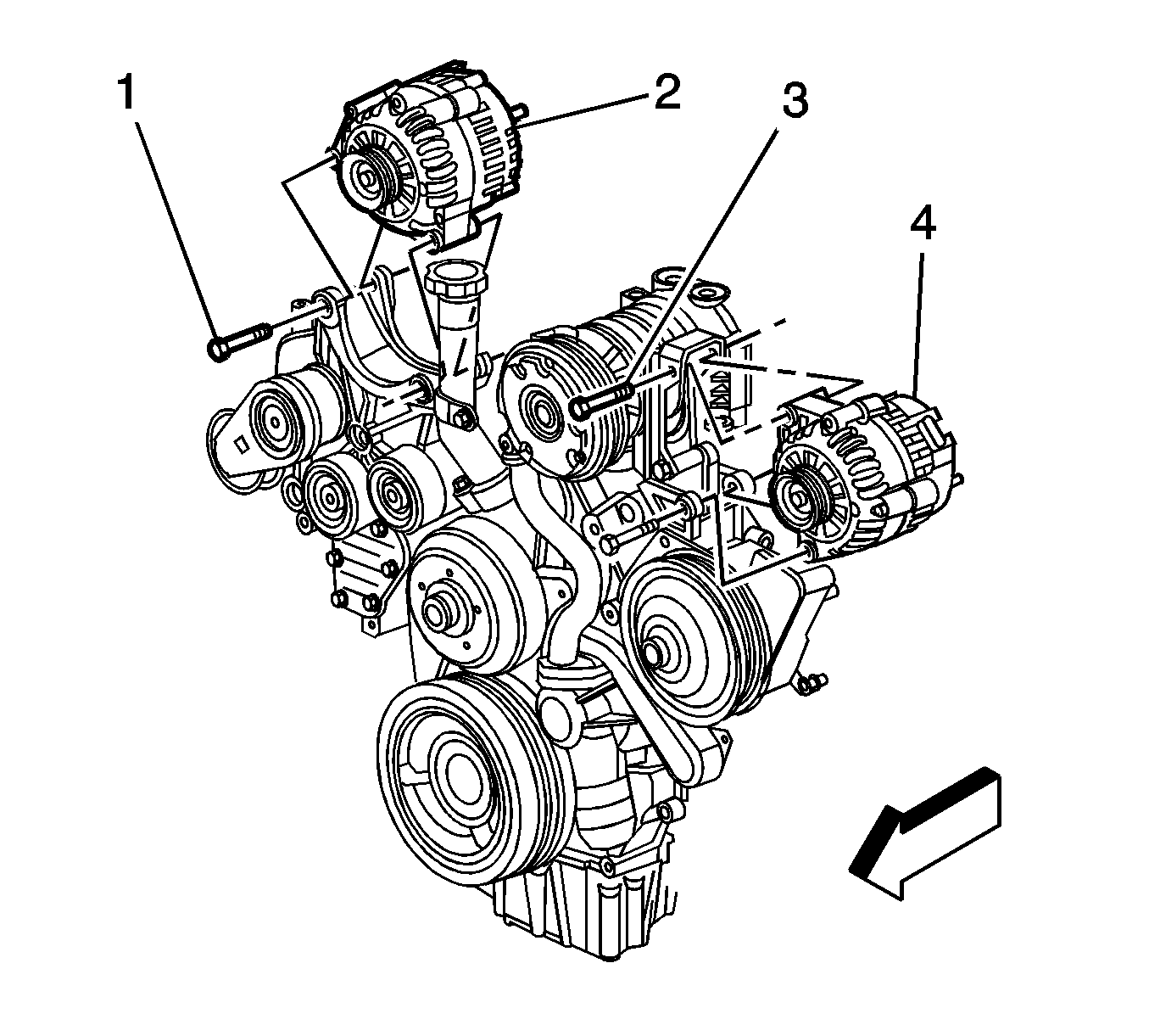
Generator Replacement 4.8L /5.3L /6.0L
Removal Procedure
- Disconnect the negative battery cable. Refer to Battery Negative Cable Disconnection and Connection .
- Remove the accessory drive belt. Refer to Drive Belt Replacement - Accessory .
- Disconnect the generator electrical connector (3).
- Remove the generator cable from the generator, perform the following:
- Remove the generator bolts.
- Remove the generator from the bracket.
Caution: Unless directed otherwise, the ignition and start switch must be in the OFF or LOCK position, and all electrical loads must be OFF before servicing any electrical component. Disconnect the negative battery cable to prevent an electrical spark should a tool or equipment come in contact with an exposed electrical terminal. Failure to follow these precautions may result in personal injury and/or damage to the vehicle or its components.
| 4.1. | Slide the boot down revealing the terminal stud. |
| 4.2. | Remove the generator cable nut from the terminal stud. |
| 4.3. | Remove the generator cable. |
Installation Procedure
- Install the generator to the bracket.
- Install the generator bolts.
- Install the generator cable to the generator, perform the following:
- Connect the generator electrical connector (3).
- Install the accessory drive belt. Refer to Drive Belt Replacement - Accessory .
- Connect the negative battery cable. Refer to Battery Negative Cable Disconnection and Connection .
Notice: Refer to Fastener Notice in the Preface section.
Tighten
Tighten the bolts to 50 N·m (37 lb ft).
| 3.1. | Install the generator cable. |
| 3.2. | Install the generator cable nut to the terminal stud. |
Tighten
Tighten the generator cable nut to 10 N·m (89 lb in).
| 3.3. | Slide the boot over the terminal stud. |
