Caution: Refer to Brake Dust Caution in the Preface section.
Removal Procedure

- Disable the park brake cable automatic adjuster. Refer to
Parking Brake Cable Adjuster Disabling
.
- Raise and support the vehicle. Refer to
Lifting and Jacking the Vehicle
.
- Remove the tire and wheel assembly. Refer to
Tire and Wheel Removal and Installation
.
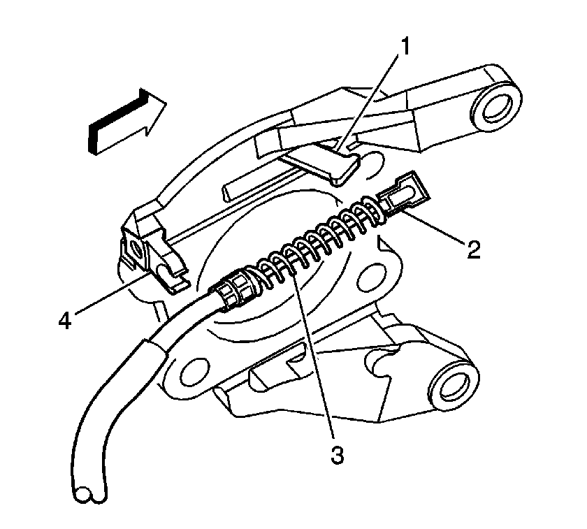
- Perform the following procedure to remove the cable (2) from the backing plate (4):
| 4.1. | Compress the spring (3) by pushing towards the lever (1). |
| 4.2. | Depress the locking tabs. |
| 4.3. | Pull the cable housing out of the backing plate (4). |
| 4.4. | Remove the cable (2) through the slot in the backing plate. |
- Remove the park brake cable (2) from the lever (1).
- For the 15 and 25 series, perform the following steps:
- For the 35 series with single rear wheels, perform the following steps:
- For the 35 series with dual rear wheels, remove the hub and rotor assembly. Refer to
Rear Axle Hub, Bearing, Cup, and/or Seal Replacement
.
- Remove the park brake shoe. Refer to
Parking Brake Shoe Replacement
.

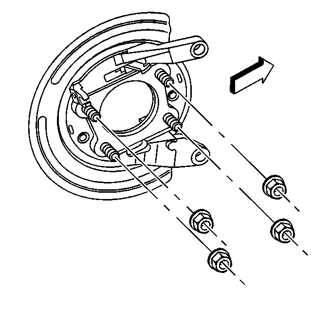
- Remove the backing plate nuts.
- Remove the backing plate from the axle housing flange.
Installation Procedure
- Install the backing plate to the axle housing flange.
Notice: Refer to Fastener Notice in the Preface section.

- Install the backing plate nuts.
Tighten
| • | Without dual rear wheels--Tighten the backing plate bolts to 135 N·m (100 lb ft). |
| • | With dual rear wheels--Tighten the backing plate bolts to 160 N·m (118 lb ft) plus 30 degrees. |
- Install the park brake shoe. Refer to
Parking Brake Shoe Replacement
.
- For the 15 and 25 series, perform the following steps:
- For the 35 series with single rear wheels, perform the following steps:
- For the 35 series with dual rear wheels, install the hub and rotor assembly. Refer to
Rear Axle Hub, Bearing, Cup, and/or Seal Replacement
.
- Adjust the park brake shoe. Refer to
Park Brake Adjustment
.

- Install the park brake cable (2) to the lever (1).
- Perform the following procedure to install the cable (2) to the backing plate (4):
| 9.1. | Compress the spring (3) by pushing towards the lever (1). |
| 9.2. | Route the cable (2) through the slot in the backing plate. |
| 9.3. | Push the cable housing into the backing plate (4) until the locking tabs snap into place. |
- Install the tire and wheel assembly. Refer to
Tire and Wheel Removal and Installation
.
- Remove the safety stands.
- Lower vehicle.
- Enable the park brake cable automatic adjuster. Refer to
Parking Brake Cable Adjuster Enabling
.


