For 1990-2009 cars only
Removal Procedure
- Raise the vehicle. Refer to Lifting and Jacking the Vehicle .
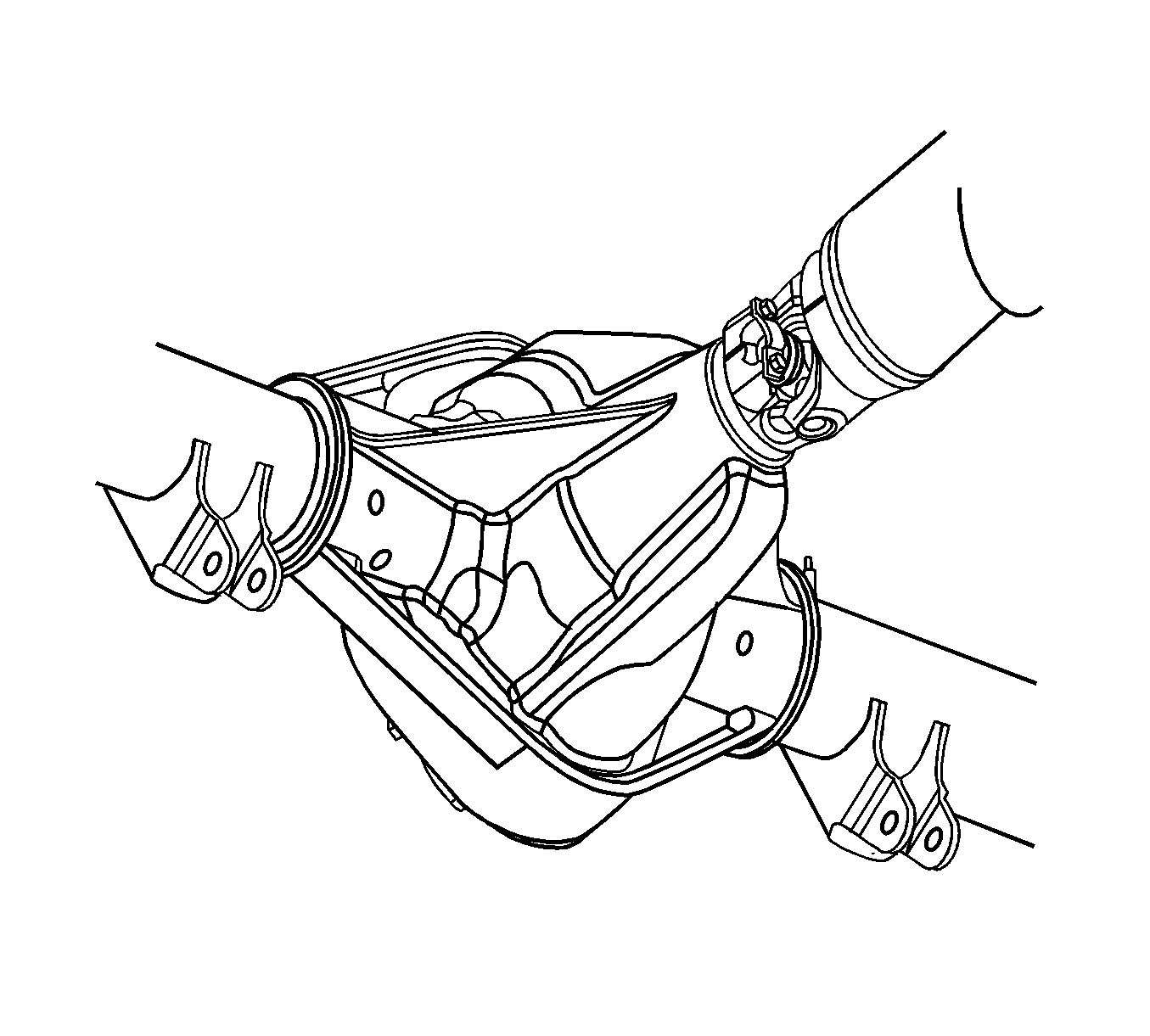
- Mark the relationship between the propeller shaft and the yoke.
- Remove the retainer bolts.
- Remove the retainers.
- Tape the U-Joint bearing caps together.
- Remove the propeller shaft from the transfer case if 4WD, or transmission if 2WD.
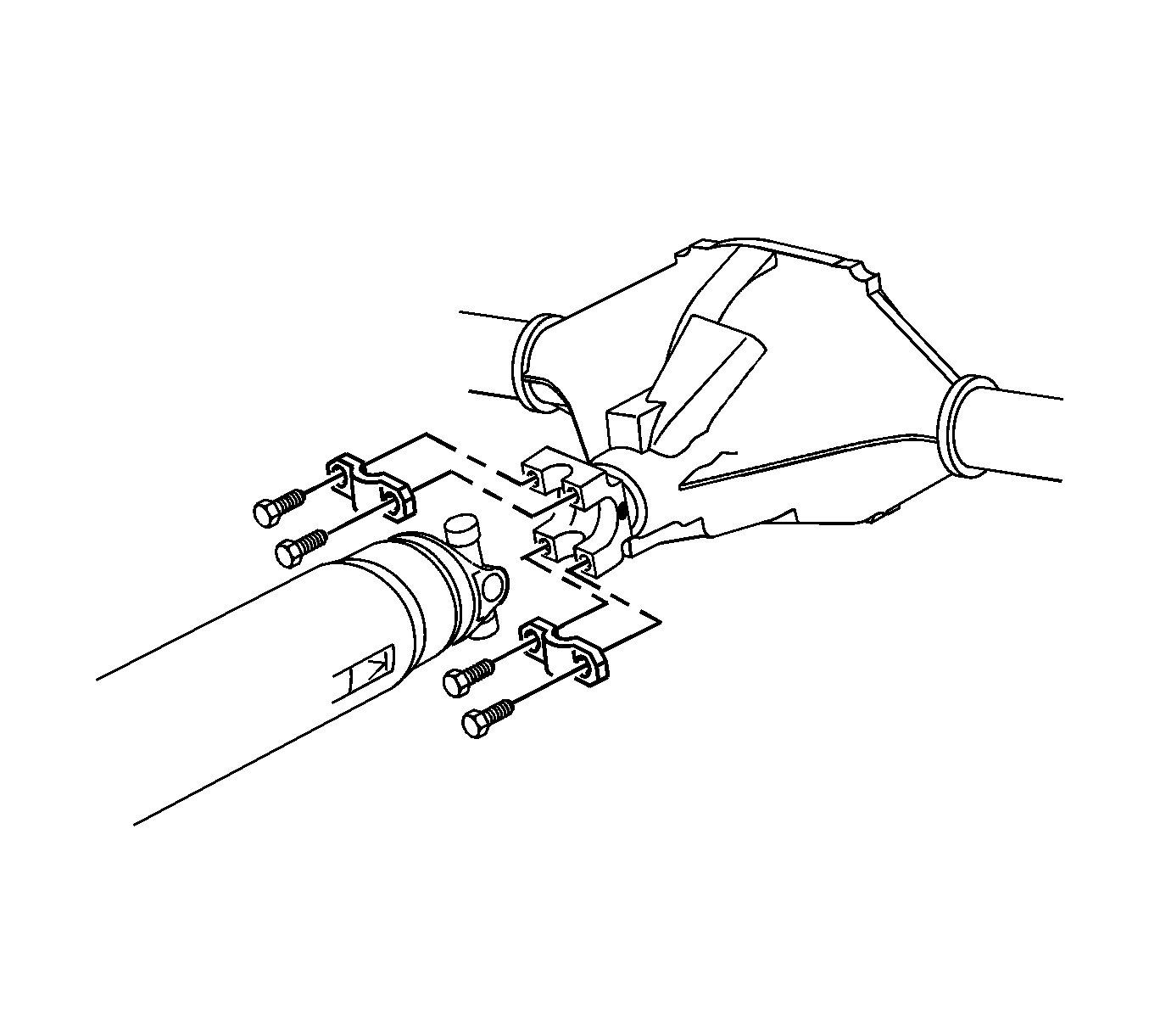
Important: The following service procedure is to ensure that the U-Joint will be properly PHASED when installed.
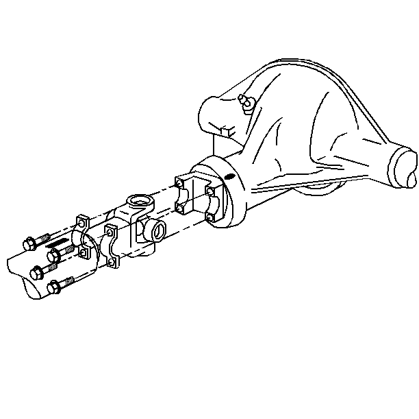
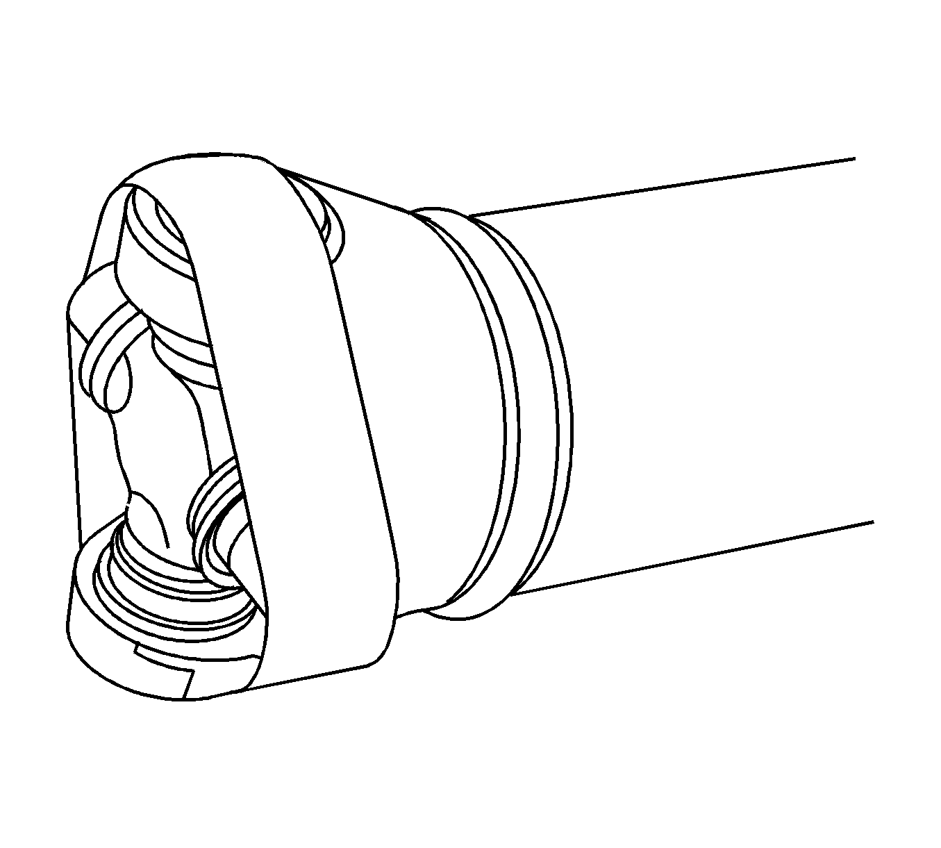
Important: The following service procedure is to ensure that the U-Joint bearing caps DO NOT become separated from the U-Joint cross and prevent the lose of the needle bearings inside the bearing cap.
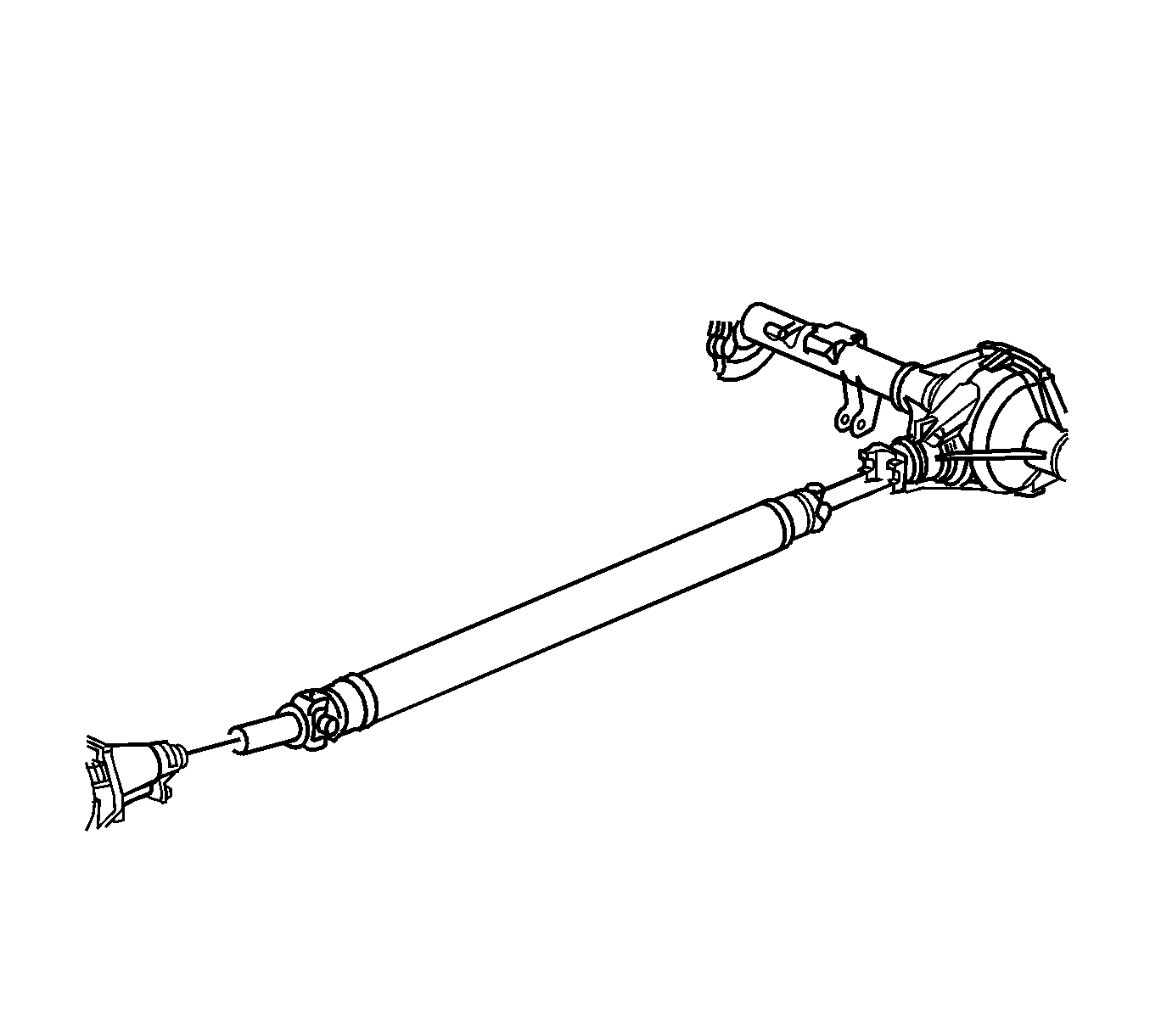
Installation Procedure
- Install the propeller shaft the transfer case if 4WD, or transmission if 2WD.
- Remove the tape from the U-Joint.
- Align the reference marks.
- Install the propeller shaft in the yoke.
- Install the U-Joint retainers.
- Install the retaining bolts.
- Lower the vehicle.



Notice: Refer to Fastener Notice in the Preface section.
Tighten
Tighten the U-Joint retainer bolts to 25 N·m (18 lb ft).
