For 1990-2009 cars only
Lower Control Arm Replacement RWD
Tools Required
| • | J 43631 Ball Joint Remover |
| • | J 45851 Ball Joint Separator Protector Adapters |
Removal Procedure
- Raise and support the vehicle. Refer to Lifting and Jacking the Vehicle.
- Remove the tire and wheel. Refer to Tire and Wheel Removal and Installation.
- Remove the front coil spring. Refer to Front Coil Springs Replacement.
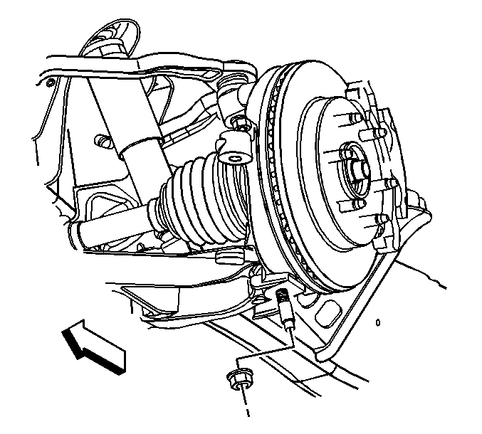
- Remove and discard the lower ball joint retaining nut.
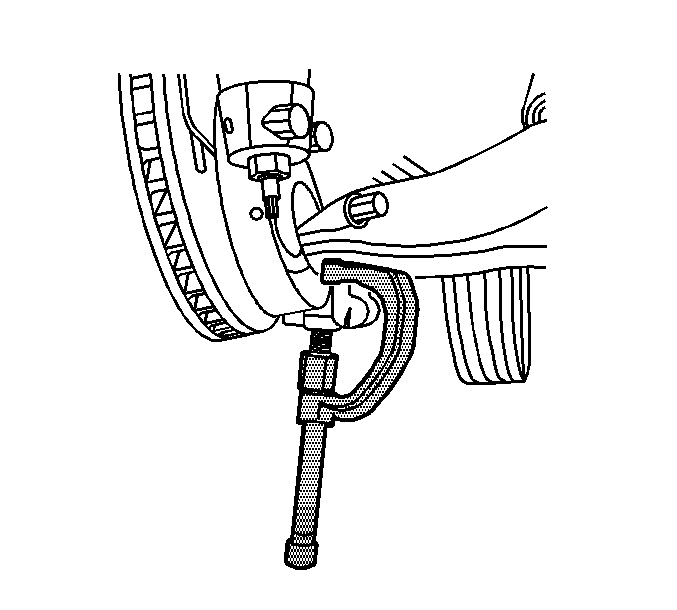
- Disconnect the lower ball joint from the steering knuckle using J 43631 and J 45851 .
- Remove the lower control arm.
Installation Procedure
- Install the lower control arm.
- Connect the lower ball joint to the steering knuckle.
- Install the new lower ball joint retaining nut.
- Install the front coil spring. Refer to Front Coil Springs Replacement.
- Install the tire and wheel. Refer to Tire and Wheel Removal and Installation.
- Lower the vehicle.
- Check the wheel alignment. Refer to Wheel Alignment Measurement.
Notice: Refer to Fastener Notice in the Preface section.
Tighten
Tighten the nut to 100 N·m (74 lb ft).
Lower Control Arm Replacement 4 Wheel Drive
Tools Required
| • | J 43631 Ball Joint Remover |
| • | J 45851 Ball Joint Separator Protector Adapters |
Removal Procedure
- Raise and support the vehicle. Refer to Lifting and Jacking the Vehicle.
- Remove the tire and wheel. Refer to Tire and Wheel Removal and Installation.
- Remove the torsion bar. Refer to Torsion Bar and Support Assembly Replacement.
- Remove the stabilizer link. Refer to Stabilizer Shaft Link Replacement.
- Remove the wheel drive shaft. Refer to Wheel Drive Shaft Replacement.
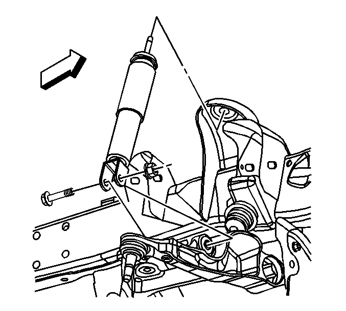
- Remove the shock absorber lower retaining nut and bolt.
- Remove and discard the lower ball joint retaining nut.
- Disconnect the lower ball joint from the steering knuckle using J 43631 and J 45851 .
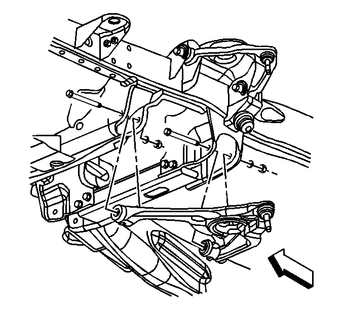
- Remove the lower control arm nuts and the washers.
- Remove the lower control arm bolts.
- Remove the lower control arm.
Installation Procedure
- Install the lower control arm.
- Connect the lower ball joint to the steering knuckle.
- Install the lower control arm mounting bolts.
- Install the lower control arm mounting nuts and the washers.
- Install the new lower ball joint retaining nut.
- Install the shock absorber lower retaining nut and bolt.
- Install the wheel drive shaft. Refer to Wheel Drive Shaft Replacement.
- Install the stabilizer link. Refer to Stabilizer Shaft Link Replacement.
- Install the torsion bar. Refer to Torsion Bar and Support Assembly Replacement.
- Install the tire and wheel. Refer to Tire and Wheel Removal and Installation.
- Lower the vehicle.
- Check the wheel alignment. Refer to Wheel Alignment Measurement.
Notice: Refer to Fastener Notice in the Preface section.
Tighten
| • | W/O 14050/12300 GVW, tighten the nuts to 155 N·m (114 lb ft). |
| • | With 14050/12300 GVW, tighten the nuts to 240 N·m (177 lb ft). |
| • | With Diesel Engine, tighten the nuts to 240 N·m (177 lb ft). |
Tighten
Tighten the nut to 100 N·m (74 lb ft).
Tighten
Tighten the nut to 80 N·m (59 lb ft).
